RF impedance matching using ferrite toroidal cores 2
Auto-Transformers
In Part 1 we dealt with transmission line transformers. We used transformation ratios which were related to a whole number greater than one squared. We were able to achieve ratios 4:1, 9:1 and 16:1 in balanced to unbalanced and unbalanced to unbalanced current formats. However, ratios and balances different from these are often required for more general application.
The auto-transformer differs from the transmission line transformer in that the transformation ratio and current balance depends on the number of windings and the particular placement of tappings along them. This arrangement convenient in that the taps may be placed at the junction of the windings which are readily accessible when wound onto a toroidal core. (See Figure 1).
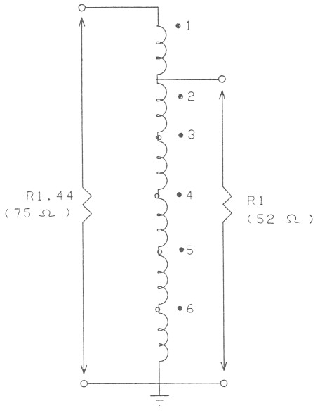
Figure 1: Represents an impedance transformation of 1.44:1 unbalanced to unbalanced. This circuit may be used to convert from 75 ohms coaxial cable to 52 ohm coaxial cable.
Determination of the number of windings and the tap positions is easy especially if you have either a calculator to provide square roots or a slide rule. I find the slide rule is easier to use in that only one operation is required to provide the number of windings and the tap position, whereas the calculator method can be rather tedious.
Now is the time to try to find your old slide rule which you thought you would never use again. (Note - the batteries will not be flat!).
PROBLEM: To convert 75 ohm coaxial cable (unbalanced to 52 ohm coaxial cable (unbalanced).
SLIDE RULE METHOD: Align 75 on the A scale with 52 on the B scale. Scan the C and D scales for integers which are aligned. 5 on the C scale is aligned with 6 on the D scale.
SOLUTION: We require a Hexifilar (6) winding which is tapped at the junction of windings 5 and 6. See Figure 1.
CALCULATOR METHOD: 52 : 75 = 52 ÷ 75 = .693 ≈ .83.
The tedious part is in converting the decimal back to a fraction to obtain the solution which is 5/6.
Unbalanced to unbalanced
It should be noted that the problem just dealt with entailed an unbalanced to unbalanced format. The windings (Figure 1) share a common grounded point at the bottom of the transformer and have an uneven turns ratio, 5:6. Consequently, current is unbalanced with respect to each winding and to ground.
Balanced to balanced
To achieve this arrangement we must have a winding configuration wherein each impedance looks into a separate but equal number of windings which, as we are dealing with an auto-transformer, will all be in series.
At this point, operation on the calculator really becomes a bore so, if you haven't found your slide rule, you should try a little harder to remember where you last saw it.
What we have to achieve is a winding/tapping ratio which is separated by an even number. If we want to match 300 ohm balanced to 75 ohm balanced we see from the C and D scales after aligning the 300 and 75 with the A,B scales that the smallest ratio separated by an even number is 2:4 - we therefore require a quadrifilar (4) winding tapped one winding either side of centre. (See Figure 2).
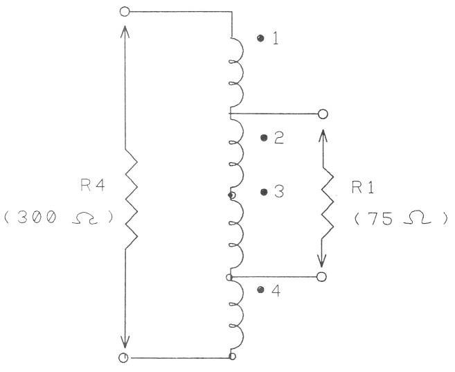
Figure 2: Represents an impedance transformation of 4:1 balanced to balanced. This circuit may be used to match 300 ohm twin feeder to a 75 ohm dipole.
Unfortunately, life was not meant to be easy!
All ratios do not provide a tapping point at the junction of windings and one must decide if an imbalance (VSWR) is acceptable or if a tapping should be placed part way along a winding. In the case of the 300 ohm feedline and the split dipole driven element of Figure 1, Part 1, where the impedance at the element centre was measured at 35 ohms, we find upon aligning A and B scales, 300/35 that the closest aligned evenly spaced integers are 2/6. They are not, however, exactly aligned. Bringing the C and D scales (2/6) into alignment causes the B scale (33.3) to move into alignment with 300 on the A scale. A resultant shift from 35 to 33.3 which gives a ratio 35:33.3 or 1.05:1 which is in fact the VSWR resulting from the impedance change. This is of no consequence as it represents a virtually imperceptible loss.
To match the beam to the 300 ohm twin feeder therefore will require a hexifilar (6) winding transformer tapped one turn wither side of centre. (See Figure 3).
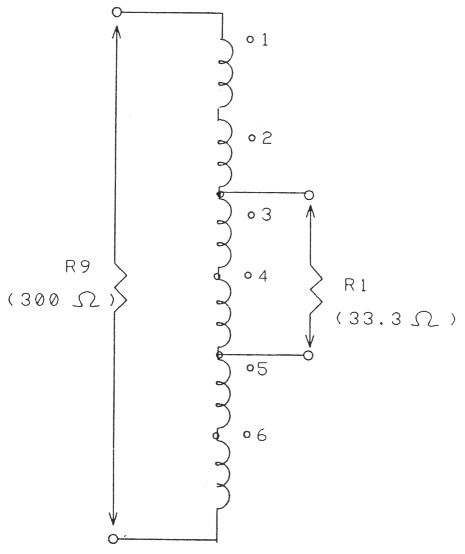
Figure 3: Represents an impedance transformation of 9:1 balanced to balanced. This circuit may be used to match a beam antenna (Yagi) with 300 ohm twin line.
Next time we will look at conventional transformers and see how they compliment and expand the variety of impedance transformations and current balance formats dealt with so far.
Part 1 - Part 2 - Part 3 - Part 4
VK3HK, Stephen Bushell