VR-tube receiver muting
Smooth break-in operation for the C.W. man.
Smooth c.w. break-in operation with a single antenna requires the use of a good keying system, an electronic transmit-receive antenna switch, and an adjustable receiver muting system. In this article W3OFU describes a combination that works well for him and should be applicable to any station with blocked-grid keying. And he also proves that good old "cut-n-try" isn't dead!
For several years the Handbook has included a differential keying system using a VR tube and a 6J5. However, neither the Handbook nor the original article(1) mentions anything about receiver muting or protection when using this keying circuit. The Handbook shows a receiver protection and muting circuit using a relay, but I asked myself, "Why not do it electronically without relays?"
The system I've worked out does just that. Used along with the t.r. switch described by W3LYP,(2) my muter gives me full c.w. break-in without clicks or thumps. I monitor my sending on the receiver with a comfortable signal, adjustable downward from S9+ to a meek S5 or less. If I choose, I can set my own signal level so it is weaker than the station I'm working.
I could make this short and merely describe the circuit of the final product, but QST editorialized recently about the need for more do-it-yourself cut-and-try spirit. That's exactly what was involved here, since my technical electronic education was a correspondence course in radio and TV that I took just for the fun of it. Perhaps you will find my efforts at design of some interest, so let's start at the beginning.
Desiring a versatile rig, last year I built the two-control job described by W3KMA,(3) using the bandbox multiplier of W1TS(4). I substituted a 6146 for the 2E26 output tube so I could have reasonable power until I could afford a good amplifier. Next, I added a remote-tuned v.f.o., also described in QST(5) and the Handbook. Not satisfied with cathode keying, I installed the VR system with the variations mentioned by W5DWX.(6) These variations permit me to use a 6C4 instead of the 6J5 and to ground the plate directly. The system works fine, and I get many compliments on the quality of my keying.
One Monimatch and a t.r. switch later, I decided I wanted to install a good method of receiver silencing. Not caring for noisy relays, I spent many hours poring through available literature. Stumped! There was nothing on electronic receiver muting geared to the VR-tube keying idea. Plenty of other ideas, but to adopt them I'd have to scrap the keying system I liked so well. Analyzing the set-up, I had a negative voltage that was being used to good advantage to grid block my oscillator and amplifier. Why couldn't it be used also to grid block another tube employed to develop a negative voltage for muting purposes? Seemed elementary enough, but how to do it? The problem resolved itself into two parts: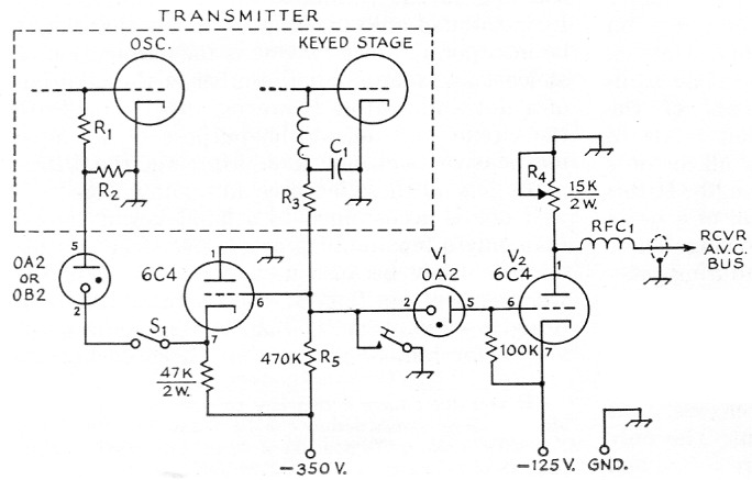
Fig. 1. Circuit diagram of the VR-tube differential keying circuit and the receiver muter (V1V2). Resistances are ½ watt unless otherwise indicated.
| C1 | Grid-block keying capacitor. |
| R1 | Oscillator grid leak. |
| R2 | 10,000 to 20,000 ohms, depending upon oscillator tube. |
| R3 | Keyed stage grid leak. |
| R4 | Key-down receiver gain control. |
| R5 | Part of grid-block keying circuit; value may differ with value of R3. |
| RFC1 | R.f. choke, 40 µH to 2.5 mH |
| S1 | V.f.o. spotting switch. |
(1) how to develop the required biasing voltage, and (2) how to trigger it properly. The answer to (1) was basic enough: use the voltage drop developed across a plate resistor with one end grounded. The whole thing could be accomplished with a tube, a small power supply, and a few resistors - except that I didn't know' what values to use for the resistors.
Here's where cut-and-try took over. With the aid of a few potentiometers in an experimental layout, I was able to develop the proper relationship between the resistance values. Using a 150-volt source, I had no trouble juggling the values to develop a voltage drop of up to 50 volts across the plate resistor. By using a potentiometer instead of a fixed resistor, I could vary this voltage drop at will. A higher voltage could be developed by changing values or increasing the source voltage, but I saw no need to do so. I had all I needed.
Next, I had to figure out how to employ the negative voltage already available in the VR keying system, use it to grid block the bias tube, and key it along with the transmitter. I tried it the hard way first, by digging into the rig and running out some experimental leads. Here's where I ran into trouble. The v.f.o. wouldn't oscillate when I took the grid blocking voltage from between the oscillator and the VR keyer tube. Taking it from the power supply side of the VR tube worked after a fashion, but gave me an uncomfortable "tail" on break. No amount of juggling circuit constants relieved this condition much.
Almost ready to give up, I decided to make one more attempt, using a simple approach. I took my cut-off voltage direct from across the key, which is in the grid circuit of the keyer tube instead of the cathode. It worked! Perfect keying, with no connections inside the rig! (At least it's perfect as far as my ears are concerned, and that's what counts.)
Operation of the muter is simple. With key up, the VR tube (V1) conducts, biasing off V2. With key down, the YR tube stops conducting and permits V2 to draw current, developing a voltage drop across the plate potentiometer. The muting voltage is varied by increasing or decreasing the resistance of the plate resistor.
How to apply the muting voltage may vary somewhat with different receivers. Mine is an RME 4350A, and the modification is simple. I merely opened up the connection to the ground ends of the a.v.c. (grid) resistors for the r.f. and first i.f. tubes and applied the negative voltage to the grids of these tubes through these resistors. The shield on the coax between receiver and muter completes the circuit to chassis. I use RCA phono plugs and jacks for my connections. To rim the muting voltage in to the receiver, temporarily I am using one of the jacks provided at the back of the receiver for the s.s.b. adapter, by removing the original connection. Since this method necessitates inactivating the a.v.c. system (which isn't in use on c.w. anyway), I intend eventually to install a regular closed-circuit phone jack.
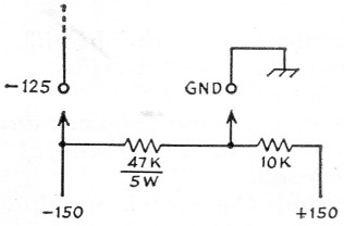
Fig. 2. If the necessary -125 volt is not available from a heavy voltage divider across the -350 volt power supply, it can be obtained from an additional 150 volt supply as shown above.
My transmitter at present runs only 50 watt input. Perhaps with higher power it might be necessary to mute an audio stage also. If so, this should be easy to accomplish. Or it may be necessary to shield and bypass the receiver to reduce direct pick-up, along the lines described recently for the HQ-129X.(7) Incidentally, I use a conventional r.f. choke and capacitor spark filter at the key; that could make a difference in how smoothly and click-free the muter works. The r.f. choke in series with the muting lead to the receiver helps in this respect. Ii used an Ohmite Z-14 which I had on hand. A regular 2.5 mH should do as well.
My silencer is built on the back part of a 5 × 9½ × 3 inch chassis, the front half being used for the t.r. switch. Parts layout is not critical. For convenience, I mounted R4 on a small panel in front above the t.r. tuning control, and to avoid r.f. pick-up ran the connection to the potentiometer through a length of shielded wire. I didn't have space in this small chassis for the muter power supply, so I used a separate 150 volt supply I had on hand with a 47K-10K voltage divider as shown in Fig. 2.
In some instances where VR-tube differential keying is already in use, the addition of V1 and V2 for receiver muting may have a slight effect on the shaping of the keying. It should only be necessary to juggle the values of C1 and R5 to restore the shaping to the desired characteristic.
Notes
- Goodman, " VR break-in keying," QST, Feb., 1954.
- Arvonio, "An electronic transmitter-receiver antenna switch," QST, Oct., 1957.
- Herring, "A two-control multiband transmitting unit," QST, Dec., 1953.
- Mix, "The 'Bandbox' - a single-control frequency multiplier," QST, April, 1952.
- Mix, "Simple remote tuning for the VFO," QST, Jan., 1953.
- "A QST-handbook rig," QST, Sept., 1956.
- Geiser, "Filtering and shielding the station receiver," QST, Aug., 1958.
Lester W. Krute, W3OFU.