New thresholds in VHF and UHF reception; Practical results
February QST(1) discussed in general terms the merits of reactance devices such as the up-converter, the down-converter, and the straight-through amplifier. As the down-converter appears to suffer from a somewhat fundamental noise figure problem, and the up-converter is, at best, equal to the straight-through amplifier but with greater complexity, it would appear that the straight-through amplifier is the most likely candidate for experimental investigation.
Some work has been done at 50 Mc, but the majority has been carried out at 144 Mc, not only due to the greater application there, but because the test equipment was readily available. It might be mentioned that similar operations at other frequencies are being carried out in about fifty commercial and government labs around the country, where vast amounts of midnight oil are being burned and black coffee consumed in attempting to reduce to practice the concept of reactance amplification.
By way of review, Fig. 1 shows the generalized circuit for a reactance amplifier. The left-hand tank serves to couple in the signal frequency and to couple out the amplified signal. The only function of the pump tank is to couple in the pump voltage which excites the diode capacitor. However, in order to obtain any amplification at the signal frequency, it is necessary for the difference frequency between signal and pump, or idler, to be terminated in a high-Q circuit. This function is performed by the tank on the right, which is resonant at this idler frequency.
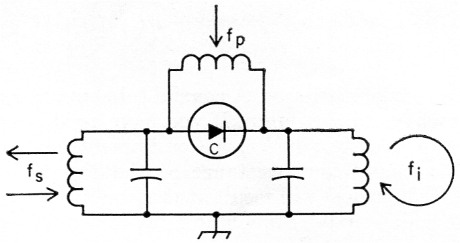
Fig. 1. Basic two-tank amplifier.
Tank Circuits
Some readers may have been wondering as to the kinds of tank circuits which are most applicable and what physical configurations are suitable. Since high tank Qs are desirable (their Qs should be much larger than the diode Qs) coaxial or cavity tanks are a natural. Also, the use of such a tank for the signal frequency allows us tp pull a sneak play and slip the idler tank into the same` physical structure. This is possible because of the higher order resonances which exist in this type of tuned circuit. Such behavior is illustrated in Fig. 2, which shows how a single coaxial resonator might be used for both the signal and idler tanks. In this example, the idler frequency is at 3fs. The diode and perhaps a small trimmer capacitor for fine tuning may be connected between the inner and outer conductors of the resonator near the end of the tank. A metal cap closing off the end would minimize radiation losses and give a somewhat higher unloaded Q.
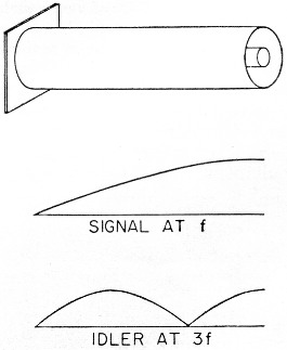
Fig. 2. Multi-mode resonator, showing how a single linear circuit may be simultaneously resonant at more than one frequency.
Various means are available with this type of tank for introducing pump power and bias voltage. A simple technique would be to inject the pump where the diode joins the outer conductor of the coaxial resonator. A coaxial cable may then be run over to the pump. If you have good judgment or are very lucky, a low impedance (low reactance and low resistance at the signal and idler frequencies) will result at the junction of the diode and coaxial connector from the addition of the pump in this manner. Otherwise, some fiddling with stubs and line lengths of the cable to the pump may be indicated. This matter will be discussed later in more detail. A series capacitor inserted at a convenient point in the circuit can be used to block the d.c. path. This will permit the bias to be applied to the diode through a resistor of high value. A % watt, one-megohm resistor will do. The bias supply should be variable, as it will be desirable to adjust the operating bias for optimum performance.
Do not be alarmed by the lack of similarity between the two-tank amplifier circuit of Fig. 1 and the physical arrangement described above. The coaxial circuitry actually behaves like the circuit of Fig. 1.
Construction and results
Two radically different types of construction were used for the 144 Mc circuits. The first is completely silver-plated, has a custom-made shield box, and is equipped with all the frills to insure ultra-deluxe type of operation. It was designed to "prove out" the principles of operation. This model may be seen in the above photograph. The other, or "cheap" circuit, shown in the photo below, might be considered to be the poor man's amplifier. It consists of not much more than a 3" × 4" × 17" aluminum box, two pieces of copper strap, a diode, and many man-hours of fiddling. It was built to determine the usefulness of junk-box construction for this application. It is of mterest that there was no discernible difference in the noise figures obtained with these two circuits - a fortunate result indeed.
The results of noise figure measurements to date using various diodes in the device are given below. Note that the average of a number of measurements is given, this being much more meaningful than selecting the best measurement out of a number.
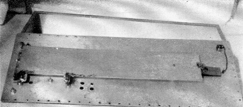
The deluxe circuit, complete with custom made shield box, is constructed of silver-plated hard copper plate, with every precaution to insure maximum Q. The resonant tank is 4" wide, 19" long, and spaced ¾" from the main plate.
| Diode | Average noise figure | Number of readings |
|---|---|---|
| MA-460A | 0.6 dB | 10 |
| S266G | 0.65 dB | 22 |
| 1N660 | 0.85 dB | 18 |
| DR-303 | 0.85 dB | 23 |
Within the tolerances set by the temperaturelimited-diode technique that was used, the results are in agreement with the theoretical limit of 0.75 dB imposed by the pump ratio. Once the region below 1 dB is reached, accurate measurement becomes quite difficult and several tenths of a decibel are not significant. For this reason no further attempts were made to optimize noise once this region had been reached!
Comprehensive on-the-air comparisons were not made; however, a brief test indicated that an improvement in received signal-to-noise ratios of the order expected was being realized. Rough checks of bandwidth made with the device adjusted for good gain and noise figure indicated values of about 100 kc.
A word might be in order here about some of the basic problems of measurement of noise figure. It is of utmost importance to maintain linearity throughout the receiving system under test. Otherwise, some rather startling negative noise figures can be obtained. Also, the a.v.c. must be turned off and gains run sufficiently low that no clipping of noise peaks occurs. This could result in indicated noise figures poorer than the true value. Considerable care was exercised in taking the measurements tabulated above. The noise generator used was home-built, but had been checked against a commercial standard.
A pitfall that may be considered to be peculiar to the reactance amplifier appears when it is attempted to pump at twice the signal frequency. This configuration may appear attractive in that the idler is equal to the signal frequency and a single, simple resonant circuit will suffice for both. Theory tells us, however, that such a pump ratio fundamentally limits us to aminimum noise figure of 3 dB; nevertheless, measurements by the noise diode method may erroneously indicate a minimum noise figure of 0 dB. The reason for this is that the noise diode is putting noise into both signal and idler channels (much as in an image response) for comparison with only the one channel of receiver noise. This means that the noise generator setting required to double the indicated output noise can be less by a factor of two; that is, it may read 0 dB instead of 3 dB. This problem disappears, of course, when the idler is displaced from the vicinity of the signal and terminated in a separate tank not coupled to the input. Results when pumping at twice the signal frequency can indeed be deceptive.
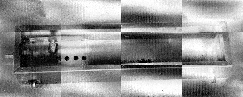
The junk-box reactance amplifier is built in a standard 3" by 4" by 17" aluminum box with the tuned circuits constructed of unplated copper strip. The small polystyrene insulator near the diode end of the box is to prevent vibration of the main tank and subsequent changes in regeneration.
Details of the "cheap" circuit are given in Fig. 3, and the circuit diagram in Fig. 4. The large, L-shaped piece of copper strap acts as the signal tank on its fundamental frequency and as the idler tank on a higher mode. The small copper strap, called the pump choke, is a quarter wave at the 900 Mc pump frequency (high impedance), but a low impedance to the signal, thus allowing maximum signal voltage to appear across the diode rather than the pump terminal. (No tuning capacitance other than the diode was used across the main tank in order to realize the greatest effective capacitance swing ![]() Adjustment, however, might be simplified by the use of a trimmer.) The button-mica capacitor blocks d.c. and allows the diode back-bias voltage to be applied to the diode through the current-limiting resistor. The signal input jack is tapped relatively high on the tank (heavy loading), while the output is tapped low (lightly loaded). The small tuned circuits in series with both these terminals are idler-frequency traps, designed to prevent loading of the idler resonant mode by the signal terminals. (The idler tank must have a high Q for proper operation.) As shown in the detail of Figure 3(B), each consists simply of a small mica compression trimmer and a short copper strap that tune to the idler frequency, 750 Mc.
Adjustment, however, might be simplified by the use of a trimmer.) The button-mica capacitor blocks d.c. and allows the diode back-bias voltage to be applied to the diode through the current-limiting resistor. The signal input jack is tapped relatively high on the tank (heavy loading), while the output is tapped low (lightly loaded). The small tuned circuits in series with both these terminals are idler-frequency traps, designed to prevent loading of the idler resonant mode by the signal terminals. (The idler tank must have a high Q for proper operation.) As shown in the detail of Figure 3(B), each consists simply of a small mica compression trimmer and a short copper strap that tune to the idler frequency, 750 Mc.
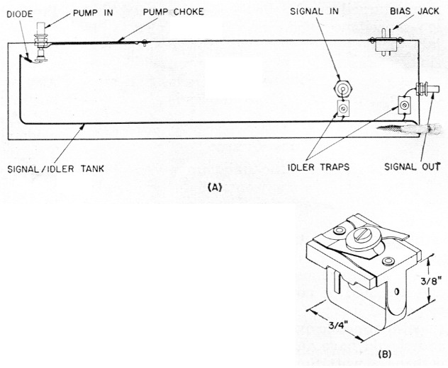
Fig. 3. (A)-Layout sketch of the junk-box amplifier, showing the L-shaped main tuner, the pump choke, and the positions of input and output terminals. For clarity, the d.c. bias lead and isolating resistor are not shown.
(B) Detail sketch of the idler trap. The 3-30 pF trimmer tunes with the 1½ inch strap to the 750 Mc idler frequency.
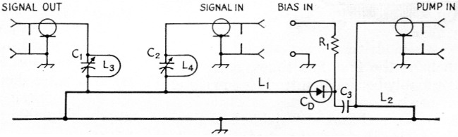
Fig. 4. Circuit diagram of the reactance amplifier.
| C1,C2 | 3-30 pF mica compression trimmer (Arco 461). |
| C3 | 150 pF silver-mica button bypass. |
| R1 | 470 kΩ, ½ watt. |
| L1 | 1/16 inch copper strap, 1 by 19 inches, spaced ½ inch. Input tapped 2½ inches, output tapped ¾ inch from cold end. |
| L2 | 1/64 inch copper strap, ¾ by 4½ inches, spaced 1/16 inch. |
| L3 | L4 1/64 inch copper strap, ¼ by 1½ inches, U shaped to fit trimmer, as shown in Fig. 3B. |
| CD | Reactance Diode. |
A few other necessary refinements include addition of a lid to prevent radiation from the line, and bypassing of the bias lead where it leaves the chassis. It might be noted that, in the experimental work, adjustable coaxial stubs were used to effect maximum transfer of pump power into the circuit. If such refinement is desired, this matching can also be done with a pi-network of trimmers and strap inductances. Tuning of these matching networks may be expected to slightly affect the idler resonant frequency.
One important factor to be considered in the design of the amplifier is that the circuit should be geared to the particular diode that is to be used. The tank circuit dimensions given here are for an operating diode capacitance of about 0.6 pF. For diodes of lower capacitance, the tank must be lengthened slightly, while for higher capacitance, it must be shortened. If this is not taken into consideration, and it is attempted to force resonance by adjusting diode bias to extremes, the pump voltage will drive the diode into either forward conduction or back breakdown. Either of these conditions is to be avoided for low noise figure. Approximate alignment can be obtained by grid-dipping the tank with a properly biased diode in place. Some changes in resonant frequency should be expected, however, when the signal terminals are attached and the pump turned on. It should also be noted that low-capacitance diodes may be paralleled to obtain the desired capacitance. However, the possibility of complex loop resonances within the parallel diodes should be kept in mind. Series operation of high capacitance diodes is also a possibility.
Pump source
Before getting into the tuning up process of one of these devices, a few words might be in order concerning the accessories. The pump source need not be crystal-controlled, but it should have sufficient mechanical stability to hold frequency to perhaps 1.0 Mc. Its thermal drift should be within the same limit after a reasonable warm-up, and it should be powered by a regulated source to prevent line voltage fluctuations. It should be smoothly tunable over about 150 Mc at 900 Mc, and should have an adjustable power output of perhaps ½ watt. Small tubes, such as the 955 and 6AF4, may be borderline for this frequency and power. A greater margin would be available with larger tubes, such as the 316A, 2C43, 8012, 5675, GL6442, etc.
Bias supply
The main requirement on the bias supply is stability, and dry batteries appear to provide the simplest solution. As virtually no current is drawn, they will last their shelf life. Two high-resistance potentiometers should be used, one for coarse and one for fine tuning. Mercury cells might also be used if higher, long-term stability is desired.
Tuning procedures
Tuning up one of the straight-through regenerative amplifiers can be a bit frustrating if you haven't done it before. There are a lot of variables and having a few extra hands would be convenient. The step-by-step procedures outlined below will be helpful the first few times, after which you will probably be able to introduce some useful variations of your own.
It will be assumed that a straight-through amplifier along the lines of the device described above has been built and is ready for tune-up. In addition to the pump and bias supply, it will be assumed that a suitable signal generator is at hand. This item will be found to be extremely useful in getting the device working properly.
Proceed as follows:
- With the signal generator and converter connected to the device, set d.c. bias to a value of about half the peak-inverse value of the diode. At this point, the pump should he connected, but should not be supplying power (B+ off).
- Adjust the signal generator to provide a moderately weak signal at the main receiver. Two or three S-units above the noise level will probably do.
- Vary bias for maximum S-meter reading. If a maximum is not found, it might be well to disconnect the signal generator and converter, and recheck for resonance with a grid-dipper. It should be possible to tune the circuit over a considerable frequency range by varying bias.
- Apply a small amount of pump power and slowly tune the pump oscillator over its frequency range. One or more pump frequencies may be found for which an increase in the S-meter reading occurs. If the device is working properly, an increase in S-meter reading means that the pump frequency is equal to the sum of the signal frequency and some idler resonant frequency - a desired condition.
- If everything is O.K. through step 4, the next objective is to increase the gain of the device to approach the point of oscillation. This is done by slowly bringing up pump power and, in turn, adjusting pump frequency and tuning (bias control) to increase the S-meter reading. It will be found that the adjustments interact on each other. For example, a change in bias affects both signal and idler resonant frequencies. Similarly, a change in pump power will require readjustment of both pump frequency and bias for maximum signal strength. This may smack of black magic and witchcraft, but it is really not too bad once you get the hang of it.
- The idler traps should be adjusted for maximum gain with a given value of pump power. There is also interaction of the idler trap adjustment on the correct settings for the other controls. Best operation is obtained by retouching the other controls after each adjustment of an idler trap.
- When the device can be made to oscillate or give very high gain, turn off the signal generator and make sure that the gain is sufficient so that an appreciable increase in the noise level results when the bias and pump frequency are tuned for maximum. A 15 to 20 dB increase in noise over that observed when the circuits are completely detuned will normally be adequate.
At this point, the device can be checked for low-noise performance using a noise diode or the signal generator. Some retuning will be necessary when a noise diode or an antenna is connected to the device if the new source impedance is appreciably different from that of the signal generator.
Miscellaneous considerations
Some suggestions can be given for the (likely) event that the device doesn't work on the first attempt. If it is not possible to obtain adequate gain when carrying out step 5, it might be well to very loosely couple the signal generator to the device. With light coupling to the signal generator, it should be relatively easy to establish oscillation or high gain in the device. This will provide an indication that there is nothing drastically wrong with the device - such as an extremely sick diode or insufficient pump power. If you get a green light indication on this check, repeat using a lower value of bias or reduced coupling of receiver or signal generator (taps closer to ground). A reduction in bias allows the available pump voltage to provide a greater capacitance swing, AC. This, however, is done at the expense of diode Q. Conversely, if plenty of pump is available, it may be possible to increase the bias and pick up a certain amount of Q. If carried too far this procedure will allow the peak of the pump voltage to swing the diode into the back-breakdown region.
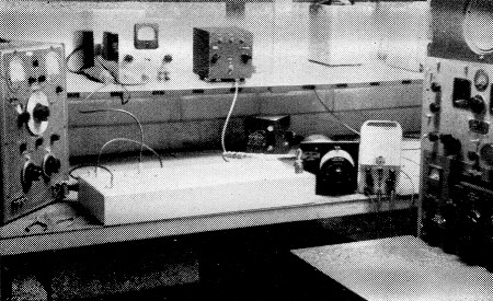
Deluxe model of the 144 Mc reactance amplifier, ready for tests on the basement workbench at W4AO.
As a rule of thumb, for minimum noise figure the antenna or signal generator should be tightly coupled to the device and the converter loosely coupled. However, if the coupling to the converter is too loose, the device will have to be operated with high regeneration and it may be difficult to maintain stable operation. The best value of coupling will, therefore, be a compromise.
If poor noise figure results and the device appears to operate normally otherwise, try to establish gain and satisfactory performance using another pump frequency. In particular, pump frequencies should be avoided which are integral multiples or close to integral multiples of the signal frequency. This point was briefly touched on in the January article(2) in connection with the single tank amplifier. Another important point, however, is that additional noise along with the spurious signals mentioned is introduced by a pump frequency which is nearly an integral multiple of the signal frequency.
It is not possible to cover all possible problems which may arise. There is one difficulty, however, which may occur in the practical operation of the regenerative devices. Stable operation might be difficult with antenna impedance variations resulting from wind, rain, and other environmental factors. If this proves to be serious, the problem could be largely avoided by using the stable up-converter configuration.
Diode hints
A few practical diode considerations might be mentioned at this point. All of the lower priced diodes have proven to be quite rugged mechanically and no appreciable change in characteristics has been observed after considerable handling. The units are known to be temperature sensitive and, if soldering is to be done within ¼ inch of the diode body, the needle-nose pliers should be used. The units are electrically stable so long as the junction dissipation is not exceeded. Safe junction dissipation ranges from 50 mW to 500 mW. (Junction power is due largely to that fraction of the pump which is dissipated in the diode resistive component.) In order to prevent possible damage due to excessive back-bias, a current-limiting resistor is placed in series with the bias supply. It should also be noted that most junctions are photosensitive and, for this reason, the majority of glass diodes are coated with an opaque lacquer. For uncoated units, it is possible that sixty-cycle modulation could be-- experienced due to fluorescent or other lights near the device. Diodes are, to a limited extent, affected by strong magnetic fields and nuclear radiation, but this is not likely to present a problem. It might also be of interest to determine the usefulness of transistor junctions as reactance elements.
It might be mentioned at this time that reactance diodes have numerous applications other than in low-noise amplifiers: They may be used for tuning v.f.o.'s, receivers, remote-tuned antennas, as phase or frequency modulators, to f.s.k. an oscillator, as frequency multipliers, frequency dividers, tunable filter elements, for panoramic receiver tuning, a.f.c., etc.
For further discussion of both the theoretical and practical aspects of reactance diodes, the reader is referred to the articles by A. Uhlir and C. J. Spector, referenced in January and February QST, and to articles by McMahon and Straube(3) and Giacoletto and O'Connell.(4)
Conclusion
In the course of the experimental work no evidence was found indicating disagreement with the basic theory of the devices. Thus, it appears that further amateur development can be undertaken with reasonable assurance of satisfactory results.
This is the concluding article of a series which, it is hoped, will help in some way to improve amateur v.h.f. capabilities. In preparing these articles, haste has taken precedence over completeness, and much work remains particularly at higher frequencies, that could not be done because of deadline factors.
Notes
- Bateman and Bain, "New thresholds in VHF and UHF reception - Circuit Theory and Diode Details," QST, February 1959.
- Bateman and Bain, "New thresholds in VHF and UHF reception - Devices and Diodes," QST, January 1959.
- M. E. McMahon and G. F. Straube, "Voltage sensitive semiconductor capacitors," paper presented at WESCON, Los Angeles, California, August 21, 1958.
- L. J. Giacoletto and John O'Connell, "A variable capacitance germanium junction diode for UHF," RCA Review, Vol. XVII, No. 1, March 1956.
Ross Bateman, W4AO
Walter F. Bain, W4LTU.