Some new ideas in a ham-band receiver
High performance at reasonable cost.
This thirteen-tube receiver covers 3.5 to 50 Mc, includes 'a ham-built lattice crystal filter, "hang" a.v.c., high-stability oscillator, and a novel product detector.
This is an 'idea" article rather than a blow-by-blow description of construction; nevertheless, there is am=' ple detail for the reasonably-savvy ham who might want to copy it. Besides ideas, the accent is on design and adjustment of the less familiar circuits incorporated in the receiver.
More and more hams appear to be discovering that they can build better receivers than they can buy, and for less money. But even if you have no intention of building a complete receiver, you may find a few points of interest in this receiver description. For example, if you have considered making a high-frequency lattice crystal filter for a receiver or sideband exciter, you will find some dope here on building and aligning it, and a circuit with an extra adjustment for extremely flat response in the passband. The h.f. oscillator is a good deal more stable than receiver oscillators usually are. Finally, the product detector has more than 300 times the gain of the double- or triple-triode circuits, and its linearity is at least as good.
Design of the receiver follows Goodman's philosophy' of keeping gain low before the "knothole" to reduce overload problems. Plug-in coils cover the amateur bands from 80 through 6 meters. The home-brew crystal filter at 4.5 Mc. gives the maximum usable selectivity for s.s.b. The a.v.c. system is very flat and works on c.w., s.s.b. and a.m. A noise limiter and a sharp c.w. filter are included in the audio circuitry.
Front end
As shown in Fig. 1, the r.f. stage uses a 6AK5, which gave better sensitivity on 6 meter than any other pentode tried. It was even superior to a cascode circuit that was used for a while. The 6AK5 is contact-potential biased to permit grounding its cathode pins directly to chassis as an aid to stability.
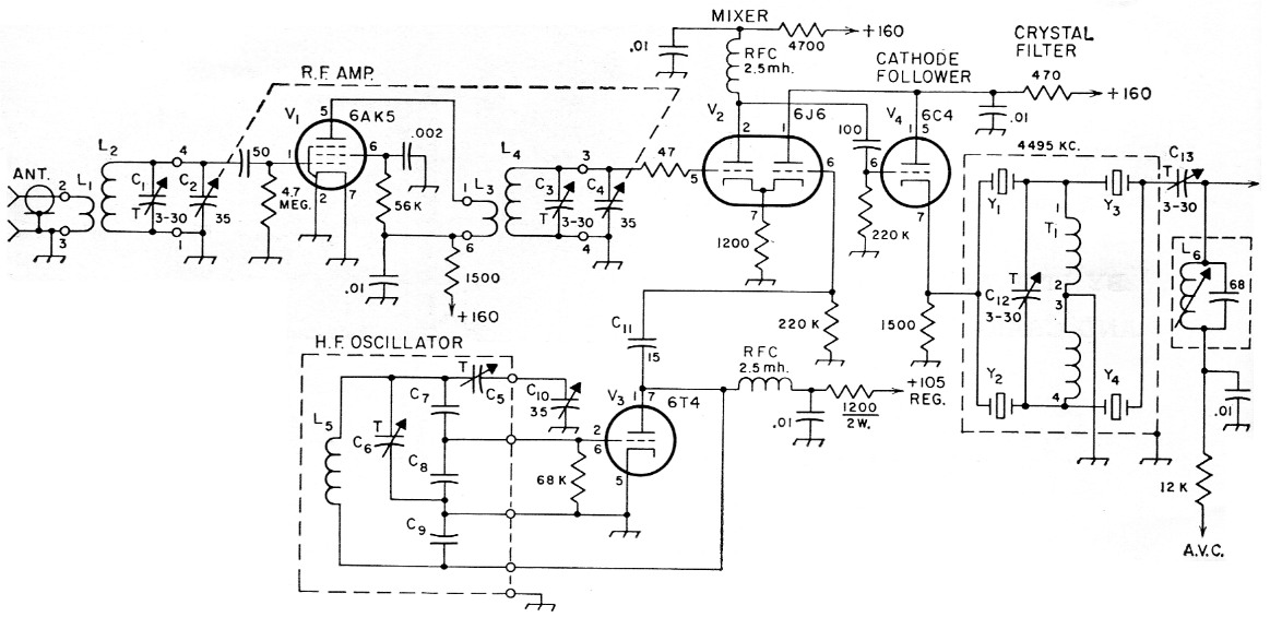
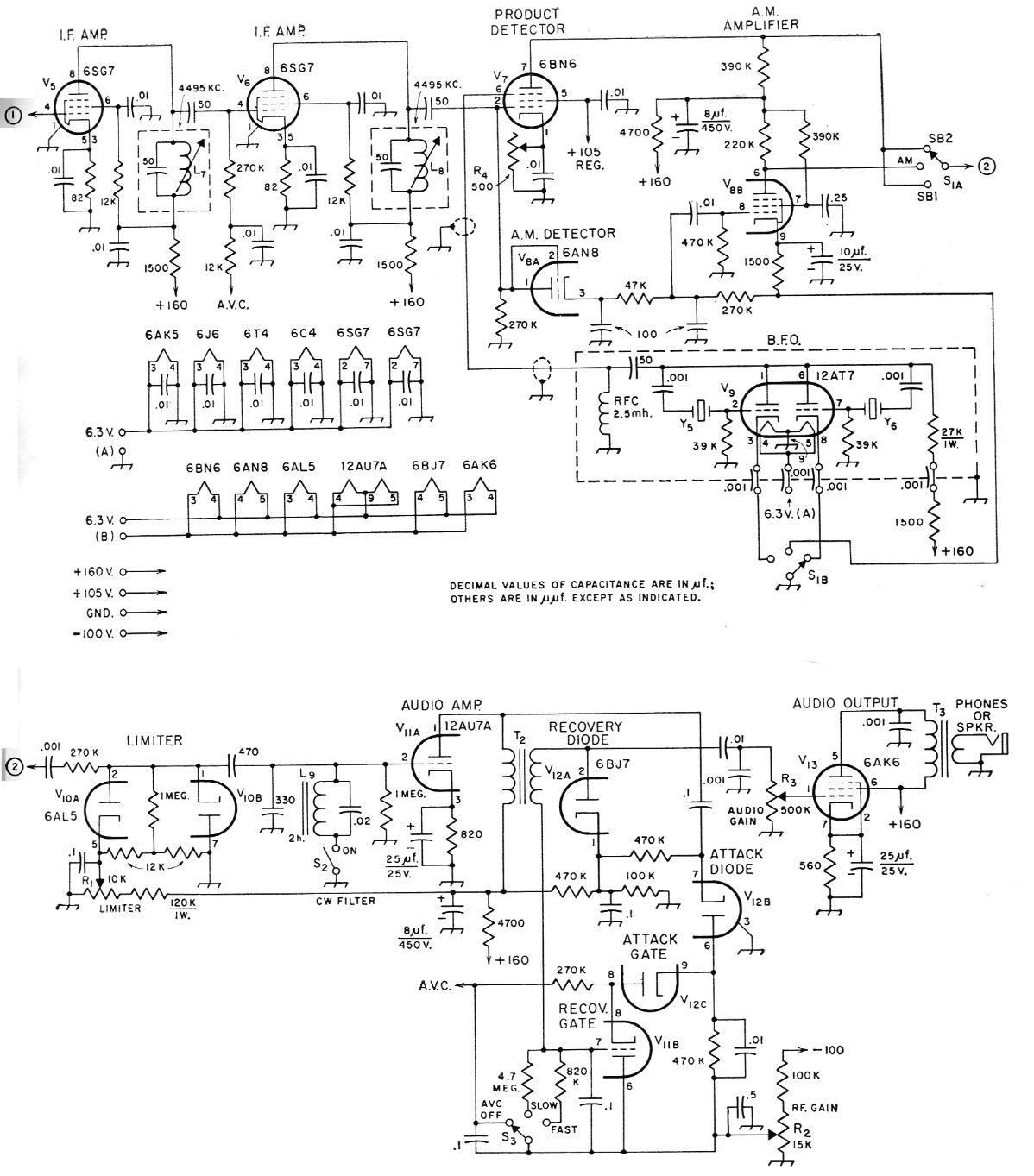
Fig. 1. Schematic diagram of the receiver, reading from top left to right to lower right. Unless indicated otherwise, resistances are in ohms, fixed resistors are ½ watt; fixed capacitors marked with polarity are electrolytic, those having values over 0.01 µF are paper, others not listea below are disk ceramic.
| C1,C3,C12,C13 | 3-30 pF mica compression trimmers. |
| C2,C9,C10 | 35 pF double-bearing variable (Bud MC-1835). |
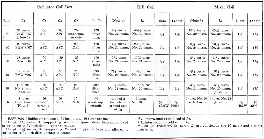
| C5-C9, inc. | See coil table. |
| C11 | 15 pF zero-temp. ceramic. |
| L1-L5, inc. | See coil table. |
| L6,L7,L8 | 15 to 25 µH; 45 turns No. 32 enam. close-wound at bottom of 3 inch slug-tuned form (CTC PLS-5), mounted in shield can (Bud 5H-294). |
| L9 | 2 H high-Q audio toroidal Inductor (UTC HQA-13); see text. |
| R1 | 10 kΩ control, linear taper. |
| R2 | 15 kΩ control, linear taper. |
| R3 | 500 kΩ control, audio taper. |
| R4 | 500 Ω control, screwdriver adjusted. |
| S1 | Rotary, 1 section, 2 poles, 3 positions. |
| S2 | S.p.s.t. toggle. |
| S3 | Rotary, 1 section, 1 pole, 3 positions. |
| T1 | Bifilar winding on ferrite toroid; see text. |
| T2 | Interstage audio, 2:1 or 3:1, secondary to primary. |
| T3 | Output, 10,000 ohm to voice coil (Thordarson 24552). |
| Y1-Y6, inc. | 4495 kc FT-243 surplus crystals, etched to frequency; see text. Y1 and Y4 have the same frequency; Y2 and Y3 are 1800 cycles higher. |
Note: Numbers on r.f. and mixer coil terminals are standard pin numbers on the coil forms and sockets. R.f. coils are on 4 prong forms (Amphenol 24-4P) and mixer coils are on 6 prong forms (Amphenol 24-6P). Coils for 50 Mc band are mounted inside coil forms.
The mixer is one section of a 6J6, cathode-biased, driven by the other section as a cathode follower. R.f. and mixer tuning capacitors are ganged and tuned by an "R.F. Peak" control on the panel.
H.F. oscillator
The art of making oscillators stable has made great strides in the last decade. V.f.o.'s for transmitters are much better than they used to be, largely because the Clapp and Vackar circuits have become popular. Receivers, though, continue to use the ancient and mostly inferior plate-tickler, grid-tickler, and Hartley circuits,(2) usually with a low gm tube such as 6C4. This seems strange, because oscillator stability is just as necessary in a receiver as in a transmitter.
This receiver uses the Vackar oscillator,(3) which has several advantages over other configurations. Like the Clapp, it is a variation of the Colpitts which steps down the tuned-circuit impedance by a capacitive voltage divider, so that variations in load or in tube capacitances are swamped by the low impedances presented to the tube. A change in heater voltage or plate voltage thus has little effect on frequency. The Vackar, unlike the Clapp, permits the oscillator cathode to be grounded to avoid 60 cycle f.m. caused by heater-cathode capacitance. Its output is more constant over a band than the Clapp's, and it does not require such a large coil on the lower-frequency bands.
The choice of tube for a Vackar or Clapp oscillator is important. A suitable tube will have high transconductance so that the impedances presented to the tube by the tuned circuit can be made lower without stalling the oscillator. Interelectrode capacitances should be small so that any changes in capacitance within the tube will also be small. Finally, the amplification factor must be fairly low to ensure adequate output voltage. The 6T4 and 6AF4 are good choices on all counts.
In this particular oscillator, a 50 per cent jump in plate voltage has almost no effect at 40 meter, and changes the beat note only a few hundred cycles at 6 meters. Pulling by the r.f. gain control is completely absent on all bands. Pulling by the r.f. tuning knob is negligible except on 6 meter and is not bad enough to be objectionable even there.
The oscillator frequency is above the signal on 80 and 40 and below it on 20, 15, 10 and 6.
Crystal filter
The heart of the receiver is the crystal filter, which was inspired by Ben Vester's article.(4) Its bandwidth is 2500 cycles between 6 dB points; final attenuation in the stop band is about 60 dB. Insertion loss is negligible - less than a decibel.
The secret of really flat passband response lies in resonating the toroid T1 (Fig. 1) with trimmer C12. Without the trimmer there was a dip of several dB in the middle of the passband. With C12 properly adjusted the response is flat within a few tenths of a decibel.
Building and aligning a crystal filter is really not so tough. It's a good idea to buy ten or twelve of the surplus crystals. The next requirement is some means of measuring the pole-zero spacings of each crystal and checking it for spurious resonances for 50 kc or so above the main response. Vester(4) outlines one method using a signal generator and the station receiver.
We didn't have a stable enough signal generator, so we haywired together a little three-tube test chassis using the circuit shown in Fig. 3A. The tunable 4.5 Mc output of the test chassis is fed to the crystal as in Fig. 4 and the v.f.o. adjusted for a peak (at the zero) or a null (at the pole) on the v.t.v.m. Since relative frequency is all we need to know, the v.f.o. is heterodyned with a crystal oscillator and the resulting audio beat measured by Lissajous figures with a scope and a calibrated audio oscillator, set up as in Fig. 3B.
Four crystals with pole-zero spacings of 1600 cycles or more and a minimum of spurious peaks should be selected for the filter. Set aside two of the remaining crystals for use in the b.f.o. The filter crystals may then be etched(6) with ammonium bifluoride solution until two of them have zero frequencies about 1800 cycles above the zeros of the other two. All four crystals should be etched high enough so that the zero of the lower pair is at least a kilocycle above the pole of the lower b.f.o. crystal. The b.f.o. crystals will be etched to exact frequency after the receiver is completed.
The filter may next be assembled in a Minibox of convenient size. In the filter assembly used in this receiver a Plexiglas plate, with holes cut in it for two octal sockets to hold the crystals, is mounted horizontally between the two long sides of the box. The number of turns on the toroid T1 should be chosen so that it resonates at 4.5 Mc with 20 to 25 pF when the two sections of the bifilar winding are connected series aiding (see Fig. 5). A Q meter or grid-dip meter is a big help here.
Preliminary adjustment of the completed filter box is made using the setup of Fig. 6. Tuning the test chassis v.f.o. through the pass-band will show two peaks, at the upper and lower ends, respectively, of the passband. These peaks will not necessarily be of equal amplitude. Set the v. f. o. halfway between the peaks and adjust C12 for maximum reading on the v.t.v.m. or scope. Don't expect the passband response to be absolutely flat at this stage. It will look better later on when the filter has been mounted in the receiver and terminated in a properly adjusted L network.
I.F. circuits
The 6C4 cathode follower after the mixer has about the right output impedance to drive the filter, which has a characteristic impedance of approximately 500 ohm. The L network (C13, L6 and the 68 pF capacitor) can be adjusted to terminate the filter properly for flat response.
The b.f.o. is crystal-controlled to eliminate the drift problem and ensure that b.f.o. frequency is set correctly with respect to the filter passband. The entire b.f.o., crystals and all, is built in a 3¼% × 2_1/8 × 1_5/8 inch Minibox, and all power leads entering the box are filtered by 1 nF feed-through capacitors. The output lead is made of miniature coaxial cable. These precautions proved to be necessary because a very little b.f.o. signal leaking into the i.f. circuits can block the product detector.
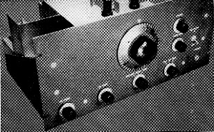
Shielding encloses the r.f. stage and mixer, along the right-hand edge of the chassis in this view. The small shield can in the far right corner has been replaced by the 6C4 cathode follower, V4, since the photo was taken. Crystal-filter box and i.f. components occupy the rear edge of the chassis, with detectors and audio stages along the left-hand edge. The 12AT7 projects horizontally from the b.f.o. shield box. The plug-in oscillator coil box is to the right of the main tuning capacitor.
Product detector
We believe that the product detector is a significant improvement over many of the circuits which have been published. It uses the 6BN6 gated-beam tube, a type originally developed for service as limiter and phase detector in f.m. receivers. The signal grid of a good product detector must be very linear so that there is no intermodulation among components of the signal. A glance at the 6BN6 curves shows that grid 1 is almost perfectly linear over a range of 2 volts peak-to-peak (0.7 volt r.m.s.), while outside this range the tube limits sharply. Grid 3 has similar characteristics except that its gain is lower.
Tests have shown that the linearity of the 6BN6 as a product detector is excellent. At 0.3 volt r.m.s. input to grid 1, the modulation recovered from a 50 percent modulated signal, measured with b.f.o. off, was 40 dB below the normal beat note obtained with the b.f.o. on. At an input of 0.7 volt the distortion products were still 35 dB down. Above 0.7 volt grid 1 was driven into the limiting region and distortion-increased rapidly. Signal input in this receiver is 50 to 100 millivolts, well below the limiting threshold.
With 3 or 4 volts of b.f.o. injection on grid 3, the 6BN6 has a conversion gain of 50 - that is, 100 millivolts of i.f. signal at grid 1 produces 5 volts of audio at the plate. By contrast, a 12AU7 in the double-triode detector circuit showed a conversion gain of 0.15 with similar input levels. Noise peaks, incidentally, are clipped by the 6BN6, leaving less work for the regular noise limiter.
The 6BN6 has one drawback - it is slightly microphonic. Trouble from this source can be avoided by mounting the tube socket on a small metal plate and bolting the plate to the chassis through rubber grommets.
Detection of a.m. signals is accomplished by an ordinary diode using one section of a 6AN8. The pentode half of the 6AN8 supplies enough gain following the diode so that one can switch from s.s.b. to a.m. without readjusting the audio gain control.
The 6AL5 noise limiter is a double-ended shunt type. It is located ahead of the a.v.c. circuits to keep noise pulses from operating the a.v.c. It also precedes the c.w. filter so that the filter will not ring on noise peaks. A shunt limiter does not clip quite as sharply as the series-diode type, but neither does it distort signals below its limiting threshold; a series limiter produces a noticeable amount of distortion on all signals.
A simple audio filter is a good way to get c.w. selectivity in a receiver of this kind, since the crystal filter knocks out the audio image, or "other side of zero beat." The tuned circuit made up of L9 and the 0.02-µf. capacitor resonates at 850 cycles. The coil specified for L9 has a Q of almost 100 and tunes as sharply as anyone could want. In fact, it rings a. little on signals; many operators might prefer a bit less Q. There are toroids available from Arrow Sales(7) with a Q of about 24, at prices considerably lower than the eleven-dollar tag on the UTC HQA-13.
A.V.C.
The "hang" a.v.c. system was taken from WOBFL's article(8) with minor modifications. The 270K resistor in series with the a.v.c. line slows down attack time enough to prevent noise peaks from operating the a.v.c. A very slight "burst" can be noticed now on the first syllable of a transmission, but it is not bothersome at all. A choice of two recovery time constants is provided. The "fast" position is occasionally useful on rapidly fading signals, but the "slow" position is used most of the time. Delay bias on the attack and recovery diodes (determined by the 470 k - 100 k divider) is set so that the i.f. signal at the detectors is about 50 to 100 millivolt, as already noted.
The principal change from Luick's a.v.c. circuit is the method of applying manual r.f. gain control. The r.f. gain knob controls a variable negative bias which is fed to the a.v.c. line in such a way that it controls receiver gain and at the same time acts as additional delay bias on the a.v.c. diodes. Thus the r.f. gain knob can be set to prevent background signals and noise from booming in during pauses, while full a.v.c. remains available to handle normal fading.
Shunt capacitors in the audio circuits are chosen so that high-frequency response drops off above 2500 cycles to reduce fatigue from high-pitched hiss. Low frequencies are cut below 300 cycles to restore balance on voice signals. The resulting audio quality is crisp and intelligible.
Construction
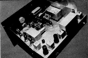
The receiver is built on a 12 × 17 × 3 inch aluminum chassis with an 8¾-inch aluminum rack panel. The top-view photo shows the layout.
The oscillator tuning capacitor, C10, is driven by a National NPW-0 dial and gear unit, through an insulated coupling. The capacitor is mounted on a 1/8 inch sheet of mica-filled bakelite, and its mounting feet are bolted to an aluminum L-bracket which is fastened to the bakelite sheet. This arrangement provides two-point support to prevent the stator from twisting. The bakelite sheet is held away from the gear box by three metal spacers and 12-24 threaded rods. The only electrical ground on the rotor of C10 is a heavy wire lead passing through a hole in the chassis and connected to a solder lug on the underside. Thus the circulating current through C10 has a single definite path so it can't wander all over the chassis looking for a route to the under surface.
The oscillator coil and associated capacitors for each band are assembled in a 4 × 2¼ × 2¼ inch Minibox (see close-up photo). A piece of mica-filled bakelite in the bottom of the box supports a row of four banana plugs which project through a rectangular cutout in the 4 × 2¼ inch surface of the box section. A fifth banana plug grounds the shield box to the chassis.
A small copper shield is soldered across the 6BN6 socket to isolate the signal grid (pin 2) from the b.f.o. injection grid (pin 6). All power wiring is done with shielded wire to eliminate one source of feedback.
The power supply is built on a separate 5 × 10 × 3 inch chassis. Its schematic is shown in Fig. 2.
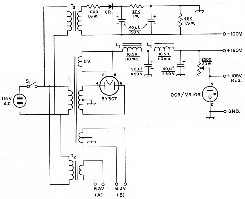
Fig. 2-Power-supply schematic.
| CR1 | Silicon rectifier, 130 volt r.m.s., 150 mA (SarkesTarzian M150). |
| L1,L2 | 10.5 H, 110 mA (Stancor C-1001). |
| S1 | S.p.s.t. toggle. |
| T1 | Power, 540 volt c.t., 120 mA; 5 volt, 3 A; 6.3 volt, 3.5 A (Stancor PC-8405). |
| T2 | Filament, 6.3 volt, 3 A (Thordarson 21F10). |
| T3 | Power, 117 volt, 20 mA (Thordarson 26R32); heater winding not used. |
Alignment
Alignment of the front end is easy, since the receiver is not gang-tuned. The i.f. stages and the L network terminating the crystal filter can be aligned with the aid of the test chassis of Fig. 3. Pull out the 6AK5 and wrap a wire from the test chassis r.f. output around the mixer coil. Set the sideband switch to the a.m. position, a.v.c. off, and connect a d.c. v.t.v.m. or high-resistance voltmeter across the 270 k load resistor in the cathode of V8A. Pull out the 6BN6 to avoid loading by its grid current. Tune the test chassis v.f.o. within the filter passband, set C13 near maximum capacitance, and peak L6, L7 and L8. Now tune the v.f.o. carefully through the passband and observe the flatness of the filter response. Adjust C13 to a slightly different value and repeak L6. Repeat this process until the passband response is as flat as possible. Set the v.f.o. to the exact center of the passband And recheck C12 for maximum signal. The filter response should be flat within about 5 per cent. Reinsert the 6BN6 and repeak L8 with the r.f. gain control set to give the smallest observable deflection on the voltmeter.
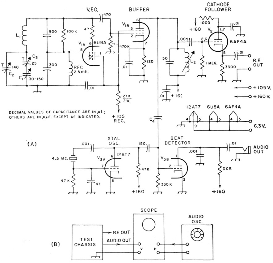
Fig. 3 (A) Circuit of test chassis.
(B) Setup for measuring relative frequency of v.f.o. Resistances ore in ohms; resistors are %2 watt. Fixed capacitors are ceramic.
| C1 | 30-150 pF variable with worm drive, taken from ARC-5 transmitter. |
| C2 | 140 pF air trimmer (Hammarlund APC-140). |
| C3 | 25 pF air trimmer (Hammarlund APC-25). |
| C4 | Two insulated wires twisted together for an inch. |
| L1 | 27 turns No. 20 enam. close-wound on 1 inch diam. form, 1 inch long. |
| L2 | Same as L6 in Fig. 1. |
When the filter alignment is complete, the b.f.o. crystals may be etched to frequency. Set the test chassis v.f.o. about 10 dB down one skirt of the filter response curve (voltage one-third of maximum). Etch the b.f.o. crystal until it is in zero-beat with the v.f.o. Do the same thing with the other b.f.o. crystal on the other filter skirt.
To check for spurious filter responses, restore the receiver to normal operation and tune in a strong modulated signal on a dead band, such as 10 meters in the evening. Tune the main dial through about 50 kc., tuning above the signal on 80 or 40 or below the signal on 20, 15, 10 or 6. Listen carefully to see if the signal appears at another dial setting. If so, the spurious response can sometimes be reduced by interchanging Y1 and Y4. It is then necessary to readjust C12.
The product detector is adjusted for best linearity by tuning in a modulated signal and setting the r.f. gain to give about 15 volts of audio at the 6BN6 plate with b.f.o. on. A modulated signal generator is best, but a voice signal will do. Disable the b.f.o. by pulling out the 12AT7 and adjust the 500 ohm resistor, R4, in the 6BN6 cathode for minimum recovered audio. There should be a sharp null near mid-range on the resistor. If the null is broad try changing the r.f. gain till you find a definite setting of the 500-ohm resistor where the signal almost disappears. A setting near maximum or near zero resistance is not correct; the tube is in the limiting region here.
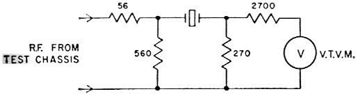
Fig. 4. Isolating network used for measuring crystal pole-zero spacing and spurious resonances. The crystal is plugged into an octal socket and the remaining socket contacts used as tie points for the '/2-watt resistors. Indicator can be a v.t.v.m. with r.f. probe or a wide-band scope.
Toroids
The only unusual item in the parts list is the ferrite toroid T1. A readily-available source of toroids, suggested by Brian Voth, W9ARZ, is the hollow ferrite core of a b.c. set antenna made by Grayburne and sold under the name Superex Ferri-Loopstick, net price 44 cents. A machinist who owns a small diamond cutting wheel can slice off a few toroids for you. It is also possible, with a little luck, to break the ferrite like a piece of glass tubing after filing a notch in it. The break may require smoothing with a file or grinder. No. 31 or 36 enamel wire is about right for the winding. The Ferri-Loopstick toroid takes about 9 bifilar turns to resonate with the 3-30 pF trimmer.
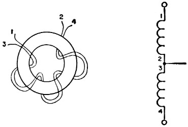
Fig. 5. Series-aiding connection of toroid T1.
Apparently almost any kind of ferrite will do for the toroid. The transformer is connected at a low-impedance point, so losses have little effect. Some rather high-loss material has been used experimentally with good results.
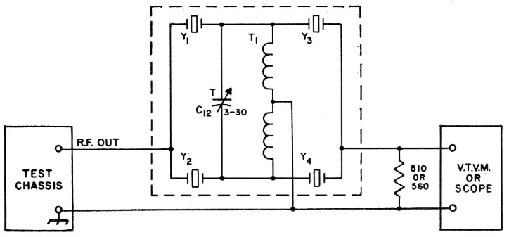
Fig. 6. Setup for preliminary adjustment of C12. Indicator con be a v.t.v.m. with r.f. probe or a wide-band scope.
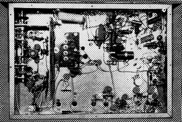
The r.f.-section tuning capacitors are along the left-hand edge of the chassis in this view of the bottom. Leads to the crystal filter go through the holes along the lower center edge of the chassis.
Results and second thoughts
The completed receiver has proved very satisfying to operate on the crowded bands. A.v.c. is remarkably flat and works equally well on side-band, a.m. or c.w. Noise figure has not been measured, but it appears to be as low as necessary even on 6 meters.
The crystal filter performs well as it is, but a possible project for the future is to add two more half-lattice sections to make it an 8-crystal filter. Skirts would be steeper, final attenuation increased, and spurious responses knocked down further.
Another idea that may be tried sometime is to replace the tuned mixer grid coils with plug-in bandpass couplers. The r.f. peaking control could then tune the input circuit to exact resonance in spite of any detuning by antenna reactance.
It is possible that a strong signal on the 4.5 Mc i.f. might get through the front end on 80 meters. A parallel-tuned trap in series with the antenna lead should take care of it. The bottom plate of perforated aluminum helps to prevent direct pickup of signals in the i.f. wiring.
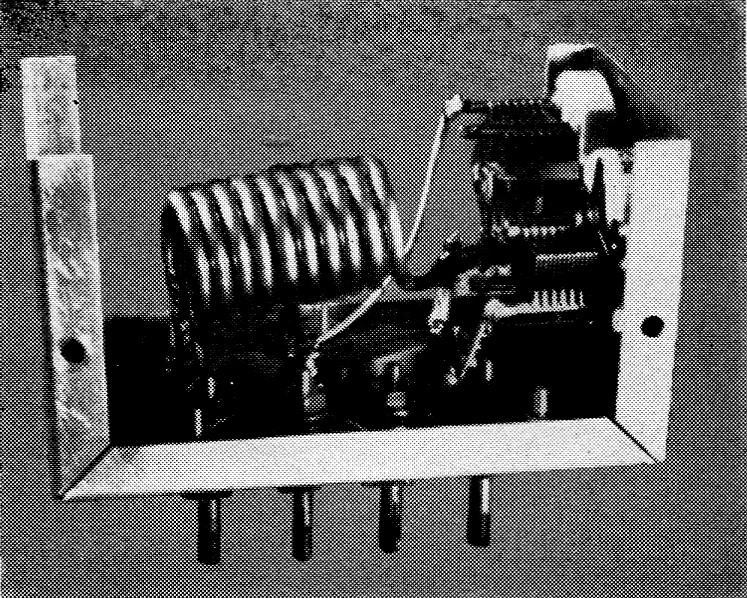
Interior of the 10-meter oscillator coil box. Layout of components in the other coil boxes is similar.
The design of this receiver was a joint project between the authors, but W9BIY did all the construction, and the set belongs to him. Any questions about details of construction or performance should be addressed to W9BIY.
We wish to thank Jim Fisk, W9GRQ, for taking the photographs and for his many helpful comments on the article.
Notes
- Goodman, "What's wrong with our present receivers?," QST, January, 1957.
- It would be perhaps fairer to say that these three circuits are often inferior, in practice, although not necessarily so in theory. It seems quite well established by now that all circuits are capable of equal stability if the same tube and operating parameters are used. However, component characteristics are generally more favorable to realization of optimum operating conditions in the case of the Clapp and Vackar. - Editor.
- Clapp, "Frequency stable LC oscillators." Proc. TRE, August, 1954, p. 1295.
- Vester, "Surplus-crystal high-frequency filters," QST, January, 1959.
- A "pole" of impedance is the parallel-resonant frequency of the crystal; a "zero" is the series-resonant frequency. The zero is lower in frequency, with the pole a kilocycle or two above it.
- Newland, "A safe method for etching crystals," QST, January, 1958.
- Arrow Sales, Inc., 2534 So. Michigan Ave., Chicago 16, Ill., and 7035 Laurel Canyon Blvd., North Hollywood, Calif.
- Luick, "Improved a.v.c. for side band and c.w.," QST, October, 1957.
Pitt W. Arnold, W9BIY
Craig R. Allen, W9IHT.