Plate modulation for the TV-set/surplus transmitter
More use of old TV sets and military surplus.
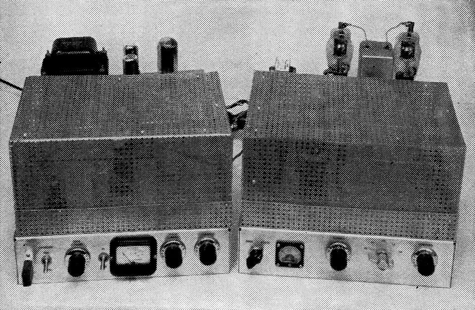
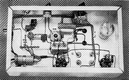
This view shows all four of the units-exciter and amplifier in the front, power supply and modulator at the rear. As mentioned in the text, considerable space and expense can be saved by incorporating the rig into a single unit.
If you've been reading QST for the last few months you should recognize two of the units shown in the photograph. The low-power transmitter appeared in March QST(1) and the 150 watt amplifier in the April issue.(2) By combining these two units and making a few changes in the power supply, a very economical 150 watt c.w. transmitter can be built. The power transformer taken from the old TV set had more than enough current rating to run the 150-watt setup - in fact, there was enough power left over to operate a plate modulator. So it was decided to add one, making a combination 150-watt c.w. or 120-watt phone rig. Also, since keeping the cost down was the primary feature of the transmitter, it was decided to try to do the same with the modulator.
A large part of the cost in building any plate modulator is in the modulation transformer. A 60 watt job (you need 60 watt in order to fully modulate 120 watt of r.f.) usually costs from twelve to fifteen dollars. In looking over the surplus market a good bet appeared to be the MD7, ARC-5 modulator, which is designed for the ARC-5 transmitters and uses a pair of 1625s, the same as the tubes in our transmitter. The MD7/ARC-5 modulator has an excellent. modulation transformer, a pair of 1625s, a 12J5 and other items that are of use. Depending on where you look in the surplus market, the MD7 can be purchased as low as four dollars for a used unit. This certainly appeared to be an ans*er to the cost question - and so it was, as ytiii can see from the photographs.
The four chassis include the exciter, amplifier, modulator and power supply. Admittedly, this takes up more room than necessary. If the builder is starting from scratch, the whole works can be combined on a single large chassis, thereby reducing the cost. Besides the lower cost of a single large chassis as compared with four small ones, you would save on coax fittings, cables, cable connectors, and other miscellaneous items.
Modulator circuit details
A 12AX7 dual triode is used as a speech amplifier in the modulator unit, Fig. 1. The original MD7 used carbon-mike input, but it was assumed that most amateurs would prefer crystal or other high-impedance microphones, so the extra speech amplifier was used. Output from the 12AX7 is used to drive a 12J5 which is transformer-coupled to the grids of the 1625s. The 1625s are operated in Class AB1. T3, the modulation transformer, has three secondary windings. One is for the plates of the modulated r.f. amplifier and another is for the screens of the same tubes. The third winding was used in the original equipment for side-tone output but is not used in this circuit. S1 is a double-pole switch that is used to short out the screen and plate windings of T3 when the transmitter is used on c.w. This serves to protect the transformer from voltage surges.
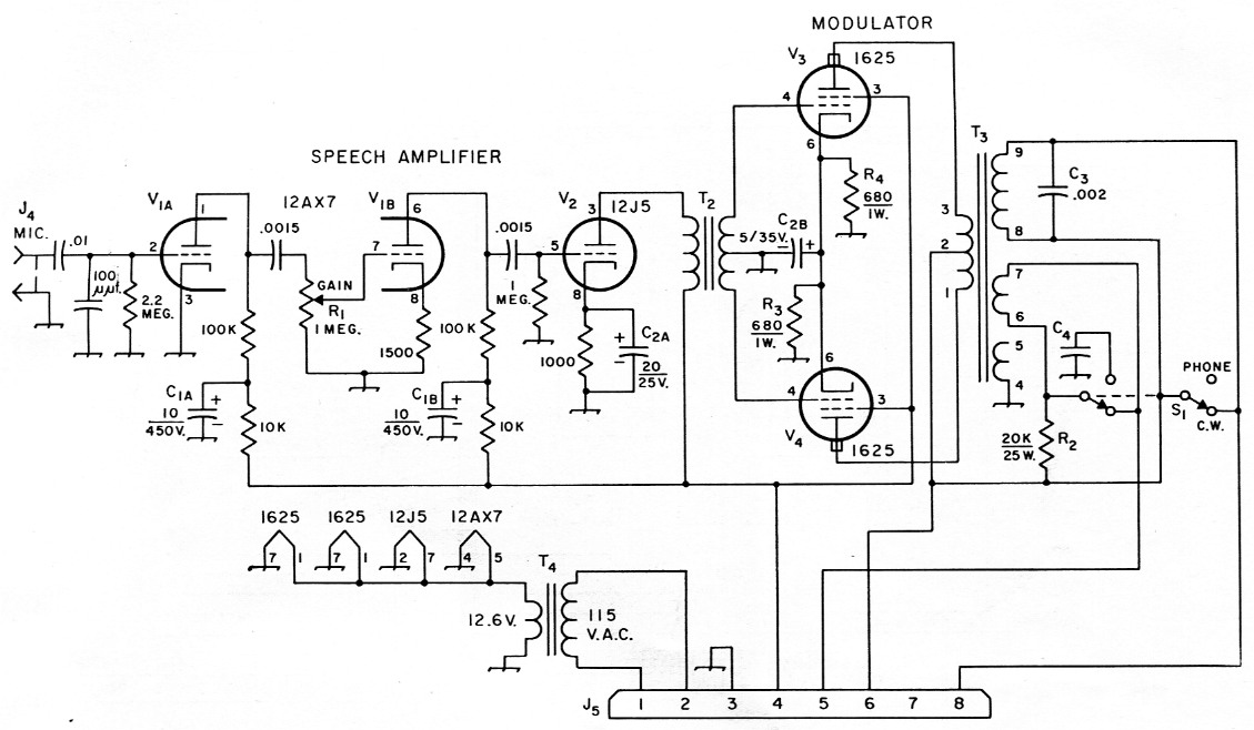
Fig. 1. Circuit diagram of the modulator unit. Unless otherwise indicated, capacitances are in µF, resistances are in ohm, resistors are ½ watt. Capacitors not listed below can be paper, mica, or disk ceramic.
| C1 | Dual 10 µF 450 V electrolytic. |
| C2 | Dual electrolytic from MD7; see text. |
| C3 | 2 nF paper or disk, 1000 V. |
| C4 | 1 1.2 µF electrolytic from MD7. |
| J4 | Microphone connector (Amphenol type 75-PC1 M). |
| J5 | Octal plug, male chassis-mounting type (Amphenol type 86-CP8). |
| R1 | 1 MΩ control, audio taper. |
| R2 | 20 kΩ, 25 W; see text. |
| R3,R4 | 680 ohm, 1 watt, from MD7. |
| S1 | Ceramic rotary, 1 section, 2 poles, 6 positions, 2 positions used (Centralab PA-2003). |
| T2 | Driver transformer, single plate to pushpull grids. Ratio 3:1 primary to ½ secondary (Stancor A-4723). |
| T3 | Modulation transformer from MD7; see text. |
| T4 | 12.6 V, 2.0 A. (Knight 61 G420, Triad F-26X, Stancor P-8130). |
The TV power transformer used in the original installation didn't have a heavy enough filament winding to carry the additional modulator tubes, so an inexpensive 12.6-volt transformer, T4, was installed in the modulator. This transformer takes care of all the tube heaters in the unit.
Power-supply details
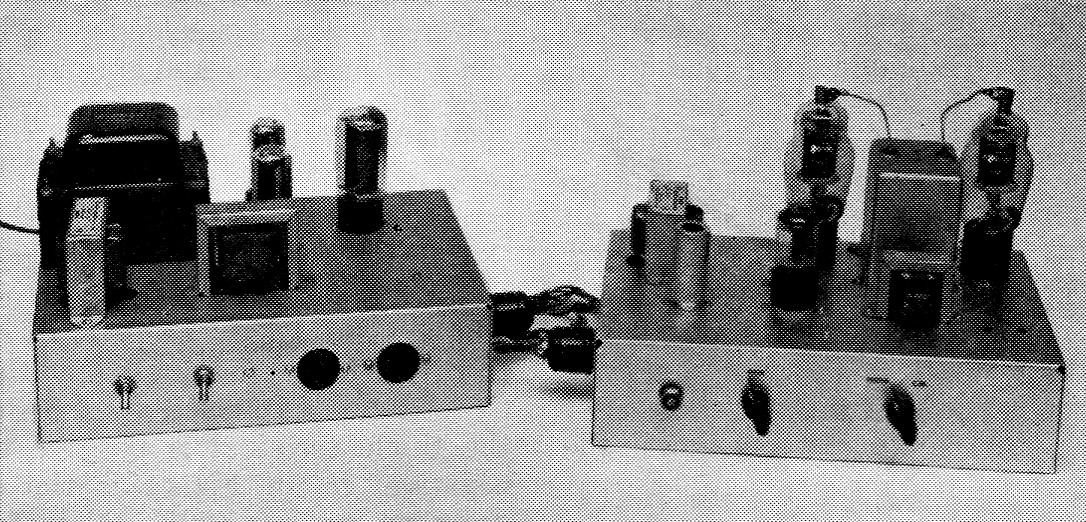
At the left is the power supply. If you compare this view with the original in April OST you can quickly identify the changes. The choke at the left front corner is L2. Across the front of the chassis from the left are S2, S3, J1, and J2. Along the top rear of the modulator chassis from the left are T4, the 1625s and the modulation transformer, T3. Just in front of T3 is T2, the driver transformer. On the front of the chassis are the microphone jack, gain control, and phone-c.w. switch, S1.
To operate the exciter and modulator, certain changes are required in the power supply as originally described in April QST. Fig. 2 shows the revised circuit of the supply. In the original circuit only a high-voltage source was needed. In the revised unit additional components, L2 and C5, are added to supply a filtered low-voltage source. This voltage, taken from the center tap of T1i works out to about half the value of the high voltage.
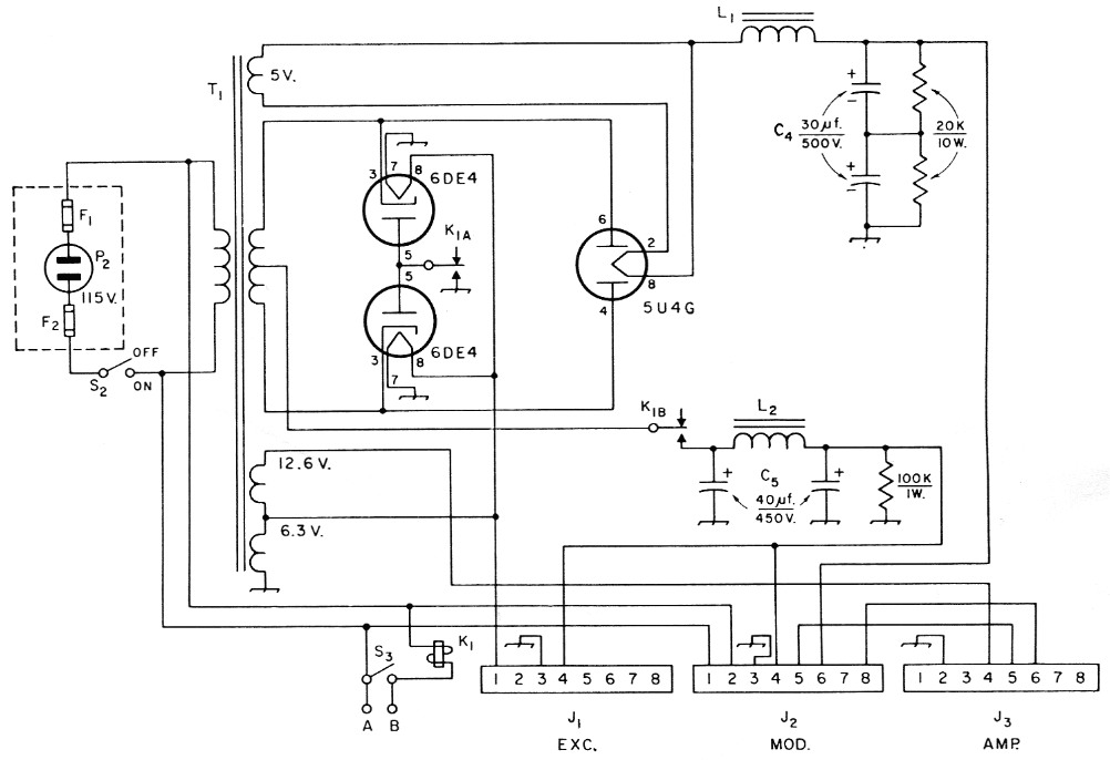
Fig. 2. Circuit diagram of modified power supply. Capacitances are in pf., resistances are in ohms.
| C5 | Dual 40 µV, 450 V electrolytic. |
| J1,J2,J3 | Octal sockets. |
| K1 | D.p.d.t. 115 V a.c. relay (Potter and Brumfield KA11AY). |
| L2 | 15 H, 75 mA. (Stancor C-1002, Knight 62G138). |
| S3 | S.p.s.t. toggle switch. |
| For other parts designations see Fig. 2, p. 22, April, 1961, QST. | |
Another addition to the unit is K1, a double-pole 115 volt a.c. relay. This relay is controlled by S3, the transmit-standby switch. The relay contacts are used to turn the d.c. voltages on and off. Some operators prefer to have the control switch mounted in a convenient spot at the operating desk. Terminals A and B on the power supply are provided so that external leads can be connected to the supply and the unit can be operated by a remote switch.
Connectors J1 through J3 are octal socket's serving as the power terminals for the cables to the three units, exciter, amplifier, and modulator.
Only two changes are required in the exciter shown in the photographs for it to be used as a driver for the amplifier. Remove one of the amplifier tubes, as a single tube will provide all the drive that is needed. The other change is to rewire the power plug (P1 in the original description) to conform with the connections of J1 in Fig. 2 of this article. Of course, if you already have a power supply built for the exciter you can use it without making any changes in the power connections.
Modulator construction
A 3 × 7 × 12 inch aluminum chassis is used to hold the modulator components. While it probably would be possible to use the MD7, ARC-5 chassis for the unit, a much neater job can be done by removing all the needed parts from the surplus unit and mounting them on a new chassis. The component layout of the modulator isn't critical, but it is a good idea to follow the general layout shown in the photographs. There are six terminals on the bottom of the modulation transformer, with an identifying number marked on the case alongside each terminal. When making the six holes in the chassis for the terminals be sure to mark the terminal number alongside the hole on the underside of the chassis, as it is easy to make a mistake when installing the unit. Incidentally, the No. 4 terminal is the case of the transformer, or ground.
The potted capacitor C2, which was taken from the MD7, is in the center of the chassis in this bottom view of the modulator. Just above C2 is R2, the screen dropping resistor that was moved from the amplifier to the modulator. At the upper righthand corner is C4, another potted capacitor taken from the MD7.
Use a piece of shielded wire between J4 and Pin 2 of the 12AX7 and ground the shield at both ends; this will reduce any chances of hum pickup on the lead. C2 is a metal-cased dual electrolytic capacitor taken from the MD7. There are three terminals on the unit. One, marked "20 µF," is the positive terminal of the 20 µF section; the case of the capacitor is the negative terminal. The middle terminal is the positive end of the 5 µF unit, and the remaining one is the negative end. C4 is a 1.2 µF capacitor, also in a metal case; the single terminal is positive and the case is negative. R2 in Fig. 1 is the original screen-dropping resistor (20K, 20 watt) used in the 150 watt amplifier. Installing this resistor in the modulator simplifies the cable wiring between the units. The only change required in the amplifier is to bring out a lead from Pin 3 of the clamp tube to P1 of the amplifier circuit. See Fig. 3 for details of this change.
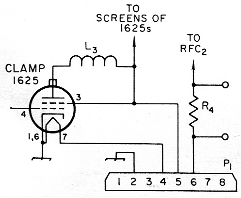
Fig. 3. Circuit modifications for removing the screen-dropping resistor from the amplifier. Designations are the same as in the original amplifier circuit (April QST).
Tune up and testing
Before applying power, check all your cabling connections carefully. In fact, if you have an ohmmeter it is a good idea to make continuity checks between the units to be sure you haven't made any wiring errors. Be particularly careful that all chassis have a common ground connection.
Connect all the power cables to the power supply, and connect the exciter to the amplifier, using a short length of coax cable. Put a dummy load on the amplifier (a 100 watt lamp will be suitable for the purpose). Put the modulator c.w.-phone switch in the c.w. position and turn on the power. Next, adjust the exciter so that you have about 8 ma. of final-amplifier grid current and then resonate the final tank. Adjust the loading on the amplifier as outlined in the previous article. However, only load the amplifier up to 120 watts input, as this is maximum rated input for plate modulation for 1625s.
Next, switch the c.w.-phone switch to the phone position and while talking into the microphone, increase the gain control, R1, until the light bulb load brightens up on voice peaks. Plate current for the two 1625 modulator tubes rests at about 50 ma. when there is no speech input and will kick up slightly - to not more than 60 mA - on voice peaks when the r.f. amplifier is being modulated 100 per cent. This plate current can be checked by opening the plate lead at the No. 2 terminal of the modulation transformer and inserting a 0-100-mA meter between terminal No. 2 and the lead that normally goes to it.
In some instances when using a clamp tube on a plate-modulated r.f. stage, it is possible to run into distortion problems because the clamp tube is not entirely curt off when drive is applied to the r.f. amplifier. Checks with a scope on this unit showed that these problems were not present with the clamp tube in the circuit.
Checking percentage of modulation requires the use of additional equipment, and it is recommended that the reader familiarize himself with the techniques by studying the modulation chapter of the ARRL Handbook.
We won't say that everyone can come up with the same figure, but judicious scrounging of parts from old TV sets and surplus gear held the price of this complete transmitting setup to less than $50.00. We think that's hard to beat.
Notes
- McCoy, "65 Watt at low cost," QST, March, 1961.
- McCoy, "Surplus tubes + an old TV set = 150 Watt amplifier," QST, April, 1961.
Lewis G. McCoy, W1ICP.