An S.S.B. product-detector adapter
Any heterodyne system, such as is employed in s.s.b. reception, responds equally well to signals on either side of the heterodyning oscillator frequency. In cases where the receiver does not have sufficient selectivity to reject the undesired image, rejection can be effected by means of an adapter employing a phasing system of the type described here.
Using the 7360 in a phasing system.
The proper demodulation of a sideband signal can be accomplished by combining it with an excess of carrier injection voltage in a diode detector or by means of a product detector. A product detector alone, however, will not reject signals on the undesired side of the injected carrier; these must be eliminated either by a selective i.f. strip or by means of a suitable phasing system and double product-detector combination. The theory of such a system is described in the ARRL publication Single Sideband for the Rili) Amateur. The adapter described is being used with an NC-125. Its cable plugs into the receiver in place of the 6116 a.m. detector. A minor modification of the circuitry was necessary that does not affect a.m. operation.
Circuit description
Two type 7360 tubes are used as product detectors, as shown in Fig. 1. Their design and application have been previously described.(1),(2) The 6AG5 injection oscillator is used to produce two 10-volt peak-to-peak 455 kc waves on the grid of each of the 7360s. The resistor and capacitor across the secondary of T2, with resistance and reactance equal, provide equal-amplitude injection signals 90 degrees out of phase. The deflecting electrodes are fed with push-pull i.f. signals biased at +25 volt. The audio output from the plates is reduced by means of T3 and T4 to a lower impedance necessary to feed the phase-splitting potentiometers, R1 and R2, at the inputs of the phase-shift networks. Here the audio signals, which were 90 degrees out of phase, are given a 90-degree relative phase shift so they are now either in phase or 180 degrees out of phase. Those in phase cancel in T3, while the others add to give useful output. The phase relations are such that only one sideband is heard. Switch S1 determines the sideband selection, the center off position resulting in double-sideband response. The low-pass filter at the output restricts the audio range to where the networks perform well but the filter could probably be omitted.
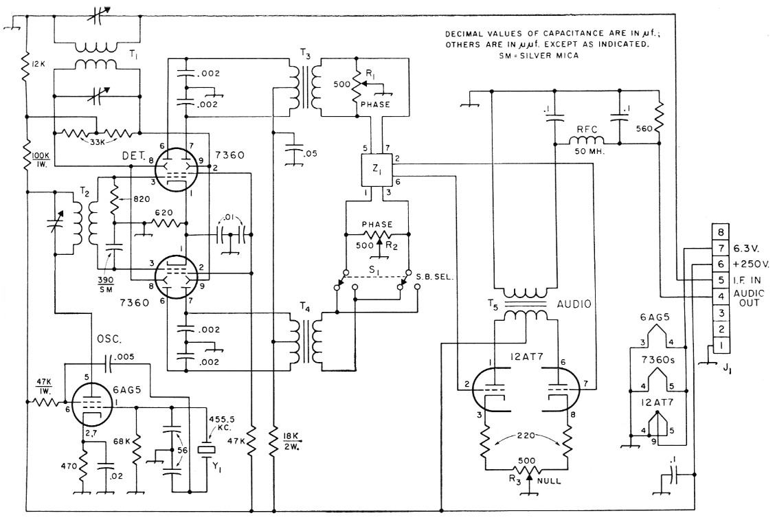
Fig. 1. Circuit of the s.s.b. adapter. Resistances are in ohm and resistors are ½ watt unless indicated otherwise.
| J1 | Octal plug. |
| R1,R2,R3 | 500 ohm control, linear taper. |
| S1 | D.p.d.t. center-off toggle switch. |
| T1,T2 | 455 kc interstage i.f. transformer (Miller 112-C2). See text for modification of T2. |
| T3,T4,T5 | Audio transformer: 20,000 ohm center-tapped to 500 ohm (see text). |
| Z1 | Phase-shift network (B & W 2Q4). |
| Y1 | Surplus crystal, 455.55 kc (FT-241, Channel 46). |
Construction
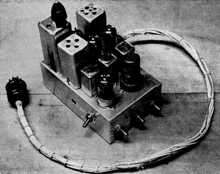
Plan view of the productordetector adapter. The i.f. transformers are at the left-hand end of the chassis, the three audio transformers at approximate center and the phase-shift unit to the right. The b.f.o. unit at the extreme left was eliminated later in favor of a crystal oscillator.
The adapter was built on a 2 × 4 × 6 inch aluminum chassis (which is a bit too small), and is connected to the NC-125 by a cable with octal connectors. Most of the parts are standard, but some are modified or surplus. The 455 kc transformers are of the capacitor-tuned variety. In T2, the tuning capacitor and half of the secondary winding were removed. The small coil was then slid to within % inch of the primary winding. The three audio transformers were obtained in surplus. Each has three center-tapped windings of 22,000 ohm, 5200 ohm, and 600 ohm, but any center-tapped 20,000 ohm to 500 ohm (or 600 ohm) audio transformer should be satisfactory provided that T3 and T4 are identical.(3)
Alignment and operation
After connecting the detector to a power source, check to see that the oscillator is working. Set T2 such that 10 volts peak-to-peak appears on each 7360 No. 1 grid.
A possible way to do this without using an r.f. probe or a wide-band calibrated oscilloscope would be to temporarily disconnect the grounded side of the 820 ohm resistor and insert a v.t.v.m. (or 0-1 milliameter) bypassed by a 100 nF capacitor between it and ground. Grid current will produce a negative voltage reading if the peak r.f. exceeds the cathode bias of about 5 volts, and the r.f. amplitude should be held below the point where this occurs.
Move the receiver tuning upward to give a 1000 cycle beat note and, using an a.c. v.t.v.m., adjust Ri so that the voltages on Pin 7 and Pin 5 of the 2Q4 are in the ratio of 2 to 7. Do the same for Pin 3 and Pin 1, using R2. Set R3 to its center, flip S1 to whichever position rejects the audio best, and adjust R2 and R3 to null out any remaining 1000 cycle tone, disregarding audio harmonics. Now tune the receiver down to 1000 cycles below zero beat, throw Si to the opposite side, and adjust R1 and R3 for a null. Repeat this several times, using only two of the potentiometers on each side of zero beat. Either this procedure or the opposite one, in which the roles of Ri and R2 are reversed, should lead to proper alignment.
In the NC-125 the wiring of the 6116 socket was modified as follows:
Pin 7 was connected to 6.3 volts a.c.
Pin 2 was grounded through the 4.3-ohm heater dropping resistor.
Pin 1 was grounded along with Pin 8.
Pin 6, which had been used as a tie point, was connected to the B+ line.
These changes leave a.m. operation unaffected, but when the adapter replaces the 6116, its input connects to the i.f. output transformer in place of the detector diode plate, Pin 5, and its output feeds in to Pin 4 in place of the series noise limiter cathode and then to the audio stages. Similar connection should be possible with many other receivers.
Notes
- Vance, "S.S.B. exciter circuits using a new beam-deflection tube," QST, March, 1960.
- Filipczak, "Using the 7360 in the HBR-16," QST, December, 1960.
- Transformers used in the W2EWL s.s.b. exciter should be suitable. See QST Ham-Ads.
Carl F. Buhrer, K2OHF.