Six meters with the TV/Surplus 150 watt amplifier
Adding a plate tank for 50 Mc.
After describing the 150 watt amplifier(1),(2) for 80 through 10 meter, several requests were received asking if the unit could be modified for 6 meter. The tubes used in the amplifier, a pair of 1625s, have ratings which permit full input up to 60 Mc, so it was decided to try the amplifier on 6. Unfortunately, it was impossible to modify the existing tank circuit, as the physical layout of the parts wasn't suitable for v.h.f.work.
Incidentally, this article is written strictly for the benefit of those hams who already have built the amplifier. If you are a v.h.f. man and want an amplifier just for 6 meters, it is recommended that you build one of the units described in the v.h.f. section of the ARRL Handbook. These amplifiers offer better design in that their physical layout of components is made for the shortest possible leads, which makes for better over-all efficiency.
In order to do the best job with this amplifier, a separate tank circuit was constructed so that shorter plate leads to the 1625s could be used. In the original unit the tank circuit was mounted below the chassis and plate leads brought up to the tubes. While long plate leads may be suitable for the lower bands, they should be avoided on v.h.f.
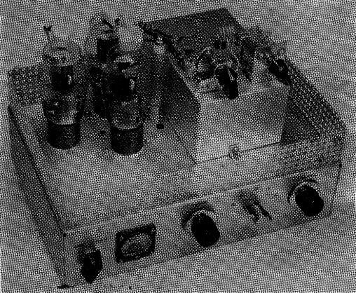
This view shows the addition of the 50 Mc tank circuit. The aluminum chassis on which the tank is mounted is to the right of the 1625 amplifier tubes.
The exciter used to drive the amplifier should have 7 or more watt output. Anything less than this will not provide enough drive, since the grid circuit of the amplifier is untuned. A previous article(2) described the construction of an inexpensive plate modulator for the amplifier and this same modulator can be used in the 6 meter setup.
Circuit details
Fig. 1 is the circuit of the new tank for 50 Mc. The 1625s are operated in parallel, the same as on the lower bands. One of the problems encountered when the circuit was tested was the presence of a v.h.f. parasitic. The parasitic suppressors used with the low-frequency tank didn't appear to do a job. After trying several combinations, the problem was solved by using a copper strap between the plates of the 1625s, plus the use of L5R5. In addition, two 10 ohm resistors, one in the grid lead to each tube, were installed as shown in Fig. 2. It was found that these steps also took care of the parasitic when the low-frequency tank was used.
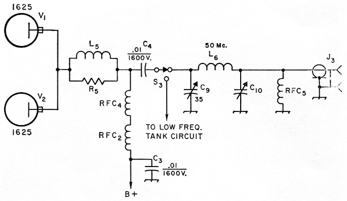
Fig. 1. Circuit diagram of the 6-meter tank circuit. Decimal values of capacitance are in µF, others in pF.
| C9 | 35 pF variable (Hammarlund MC-35-S). |
| C10 | 365 pF or more, variable (Miller No. 2111, Allied Radio 61-H-009). |
| L5 | 4 turns No. 20 wire wound on 100 ohm, 1 watt resistor, turns spaced to cover length of resistor body. |
| L6 | 5 turns No. 12 wire, ½ inch diam., turns spaced wire diameter. |
| RFC4,RFC5 | 50 Mc r.f. choke (Millen 34300-22, Ohmite Z-50, National type R60). |
| R5 | 100 ohm, ½ watt. |
| S3 | Homemade switch; see text. |
| J3 | Coax chassis receptacle, type SO-239. |
| For other circuit designations, see April, 1961, QST.(1) | |
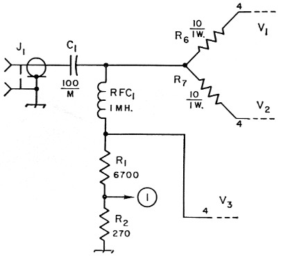
Fig. 2. Circuit diagram of modified grid circuit for the 1625 amplifier. R6 and R7 are 10 ohm, 1 watt, composition-type resistors. Do not use wire-wound. Other values are from the April, 1961, QST article.
The r.f. choke used in the original circuit was not designed for 6 meters, so a more suitable choke, RFC4, was connected in series with the low-frequency unit. C9, Ls, and C10 make up the pi-network tank. Band changing from the low-frequency tank to the 6-meter unit is accomplished by switching the coupling capacitor C4 to whichever tank is used. In order to save cost and simplify the circuit, the switch for this purpose consists of a flexible lead and a Fahnestock clip, as detailed in the next column.
Construction
The 6-meter tank circuit is mounted on top of a 3 × 4 × 6 inch aluminum chassis. This chassis is installed on top of the amplifier deck in the open area alongside the amplifier tubes, as close to RFC2 as possible. The 6-meter chassis can be secured to the amplifier top either by using self-tapping screws or by making up right-angle brackets. The perforated shield used to cover the amplifier tank circuit on low frequencies is removed for 50-Me. operation.
A four-terminal bakelite tie-point strip should be mounted on top of the chassis close to RFC2. One of the terminals is used for the junction of L5, RFC4, and C4. The other end of C4 is connected to the adjacent terminal. Also connected to this terminal is a short piece of flexible lead (or metal braid) which is terminated in a Fahne-stock clip. This is the "arm" of S3. Pieces of tinned wire - No. 14 or 16 is suitable - are soldered to each of the next two terminals and the wires dressed so that a length of about ½ inch projects up from the terminal lug. These are the "contacts" of S3, and the Fahnestock clip can be slipped onto the appropriate wire to make contact to whichever tank circuit is to be used.
The 50 Mc coil, L6, is mounted between the stators of C9 and C10. J3 is mounted on the rear of the 50 Mc chassis.
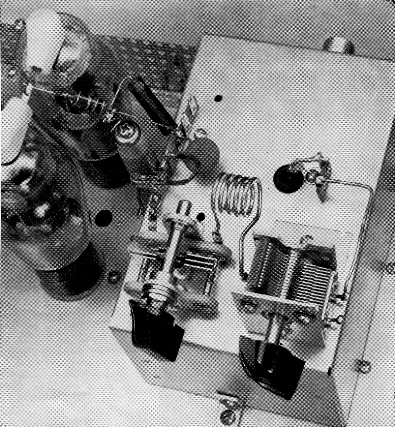
The variable at the left is the tank tuning capacitor and the one on the right is the loading capacitor. The tank coil is installed between the stators of the two capacitors. To the rear of the tank tuning capacitor is the terminal strip that holds S3, the homemade switch. Note that the plate caps of the 1625s have a short copper bonding strip connecting them together.
Tune-up procedure
Tuning up on 50 Mc with a pi-network circuit is just about the same as with the lower bands. You can use a 100 watt lamp bulb for a test load. First, tune your exciter for grid drive, a meter reading of about 8 mA being sufficient. We used the "Tech Special,"(3) which has about 7 watt output on 50 Mc, to drive the amplifier. At first there wasn't enough drive, so a ¼ wavelength piece of RG-58/U coax (about 40 inches) was used to couple the exciter to the amplifier. This got the drive up to 8 mA. If your exciter provides only marginal drive, you may have to experiment with different lengths of coax for coupling the exciter to the amplifier.
Be sure that the plate voltage is off before making any tank circuit connections. Then connect S3 so that the 50 Mc tank circuit is being fed, set C10 to maximum capacitance, and turn on the plate voltage. Tune C9 for a dip in plate current and then start decreasing the capacitance of C10, keeping the amplifier in tune by adjusting C9. The light-bulb load should light up and you can bring the loading up to about 100 watts input for phone or 120 watt for c.w. Tune-up procedure with a feed line attached is similar, but you'll probably find the settings of C9 and C10 differ from those with a lamp load.
The efficiency of the amplifier on 6 is a little better than 50 per cent. While this isn't as good as the lower bands, it is a fair output for an amplifier designed to cover several bands.
Notes
- McCoy, "Surplus tubes an old TV set = 150 watt amplifier," QST, April, 1961.
- McCoy, "Plate modulation for the TV set/surplus 150 watt amplifier," QST, July, 1961.
- McCoy, "Tech Special," QST, June, 1960.
Lewis G. McCoy, W1ICP.