A complete two-band station for the V.H.F. beginner 3 - The modulator, power supply and standing-wave bridge
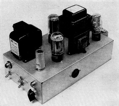
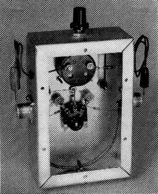
The central unit in the v.h.f. station combines the modulator, power supply and control circuits. In the right front portion of the chassis are the 12AX7 speech amplifier (shielded) and 6L6G modulator tubes. At the left is the power-supply filter choke. Near the middle of the chassis are the rectifier tube and the modulation transformer. The power transformer and regulator tube are at the back. Receiving and transmitting assemblies plug into sockets in the sides of the chassis.
In describing equipment serially, as is being done here, the author inevitably runs into the problem of covering the various items in a logical manner. There is no adequate solution to this in connection with our v.h.f. station. If you build the tuner first, you have no power to run it, and if you make the power supply and control system first, you have nothing to use it on. The transmitters cannot be operated without the power supply; and if you have built the equipment in the order we have described it, you still cannot operate - the v.h.f. converters are yet to appear! But have patience; the gear is all completed and working nicely. The trouble is that it would take an entire issue of QST, if we were to describe it all at once.
Construction of the units described herewith will put you on the air, with phone or c.w., on 50 and 144 Mc, and the station will be complete with all necessary controls and test equipment for transmitting. The main item of interest this time is a modulator, speech amplifier, power supply and control unit. It is the central item of the station, designed so that the transmitter r.f. assemblies plug into its left side and the receiving gear into the right side. In the audio portion a 12AX7 dual triode speech amplifier drives a 6L6G modulator. The microphone may be either crystal or high-impedance dynamic. The power supply for the entire station is included, as are the circuits for send-receive switching. A coaxial antenna change-over relay is mounted on the rear wall. The standing-wave bridge and test meter is a separate unit that will also be described in this issue.
Building the control unit
The chassis is 7 by 12 by 3 inches in size. Layout of parts is not critical, so no template for drilling this chassis has been made. If the general physical arrangement shown in the photographs is used there should be no problems encountered in building the unit. Looking at the oblique view, we see the speech amplifier tube in the foreground. To the left is the filter choke. In back of the 12AX7 is the 6L6G modulator, and in line thereafter are the modulation transformer and the voltage-regulator tube. At the rear of the picture are the rectifier tube and the power transformer.
On the front wall at the left are the main a.c. switch, S1, and a red pilot light. The upper of the two toggle switches is the dual send-receive control, S2. This switches the high voltage from transmitter to receiver, and also applies a.c. to the coaxial relay, which is mounted on the back of the unit (see bottom view). The second switch, just below the send-receive control, is used to apply voltage to the receiver while the transmitter is on, if desired. This enables the operator to monitor his transmissions, and also can be used for duplex operation (above 51 Mc) if separate transmitting and receiving antennas are used. More on this later. At the right are the microphone connector and the gain control for the speech amplifier.
From the bottom view it is obvious that there is plenty of room for the parts. All leads that are not part of the components themselves are made with shielded wire (Belden 8885). This may not be entirely necessary, but it is a good precaution against r.f. feedback and hum troubles. Liberal use of terminal strips makes for a neat and trouble-free unit. Note that there are octal power sockets on each side of the chassis. These carry the heater and plate voltages for the transmitters, J3, left, and receiving gear, .12, right, as the unit is viewed from the front.
In the bottom view the coaxial relay is seen on the rear wall of the chassis. Note that the a.c. terminals are bare in this picture. Before the unit is put into service these leads should be covered securely with plastic tape or insulated sleeving. The coaxial connectors come in close proximity to them when the cables are connected, and a shock is likely if the relay terminals are not protected. In the upper left of the picture is the power transformer. Below it are the regulator tube socket and one of the electrolytic filter capacitors. This capacitor was added during the testing of the equipment, only the dual 8-µf. capacitor at the upper right having been included originally. A triple 8 µF 450 volt capacitor or three separate 8 µF 450 volt capacitors can be used equally as well. The modulator and speech-amplifier components are at the lower right of the bottom view. The main control switch and pilot socket are in the upper right.
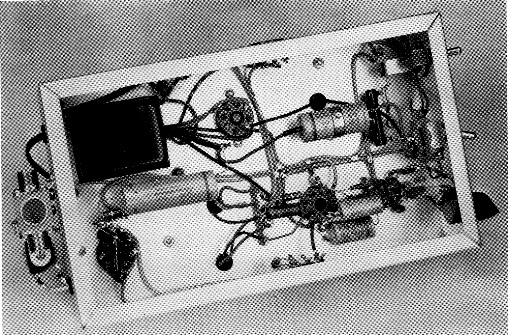
Bottom view of the modulator and power-supply assembly. Note the coaxial antenna changeover relay mounted on the rear wall of the chassis.
In the schematic diagram, Fig. 5, the main control switch is shown in the off position. When it is closed, the power circuits are activated, applying filament and plate voltage to the rectifier, and heater voltage to the modulator and to whatever equipment is plugged into it. The send-receive switch, S2, is shown in the receive position, which is the way it should be left when the station is turned off. With the power on, 150 volt, regulated, is applied to the amplifier and detector tubes in the tuner and to all tubes in the converters, through Pin 6 of socket J2. The audio stage in the tuner receives its high-voltage d.c. through Pin 2 of J2. When 82 is in the send position, a.c. goes to the coil of the coaxial relay, K1, and high-voltage d.c. to the transmitter through Pin 2 of socket J3, and to the speech amplifier and modulator tubes.
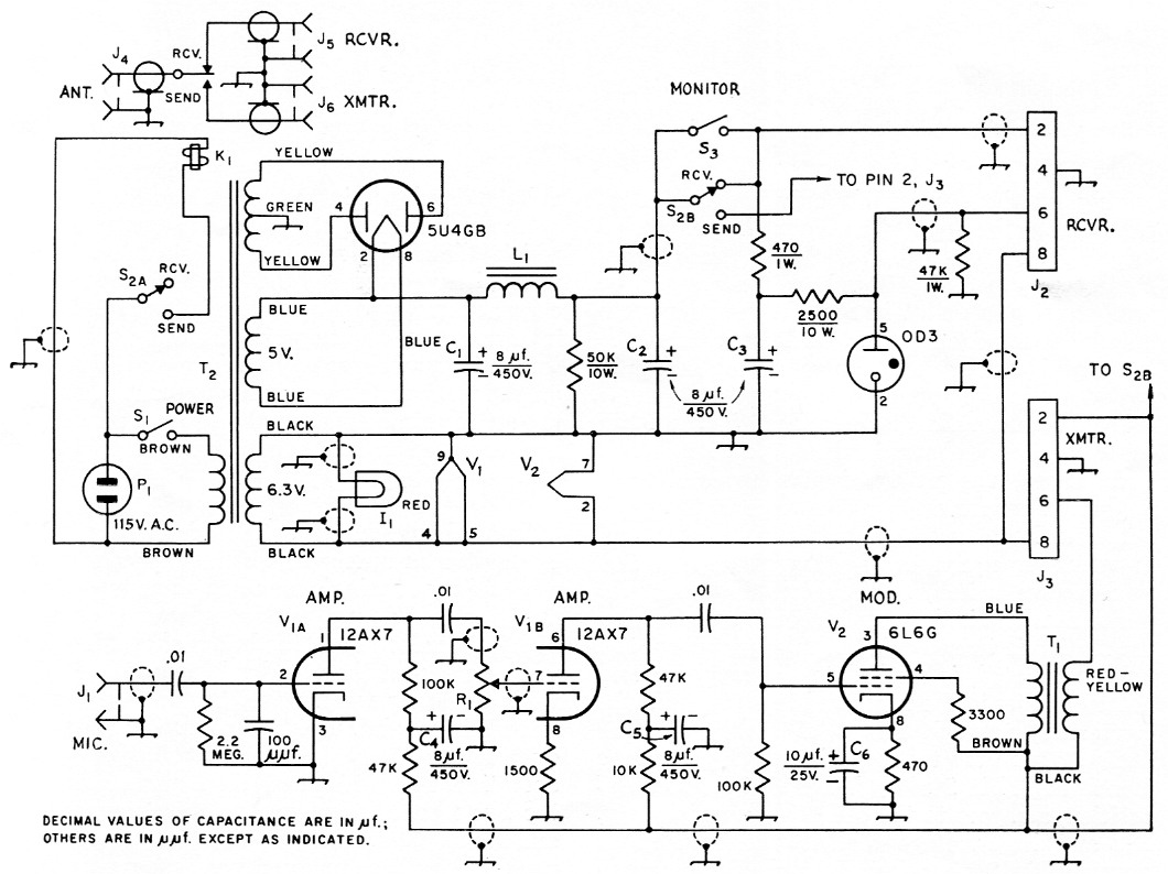
Fig. 5. Schematic diagram and parts information for the modulator and power supply. Capacitor values in µF unless otherwise indicated. Resistors ½ watt unless specified.
| C1-C5 incl. | 8 µF 450 V electrolytic. C1, C2 and C3 can be separate or combined in one housing. |
| C6 | 10 µF 25 V electrolytic. |
| I1 | Pilot lamp and socket. |
| J1 | Microphone connector (Amphenol 75-PC1 M). |
| J2,J3 | Octal socket (Amphenol 77-MIP-8). |
| J4,J5,J6 | Coaxial fittings on relay K1. |
| K1 | Coaxial antenna change-over relay, 115 volt a.c. |
| L1 | 4.5 H 200 mA filter choke (Stancor C-1411). |
| P1 | 115 volt plug. |
| R1 | 500 kΩ control, audio taper. |
| S1,S3 | Toggle switch, s.p.s.t. |
| S2 | Toggle switch, d.p.d.t. |
| T1 | 20 watt modulation transformer, pri. 10,000 ohm, sec. 3, 5, and 8000 ohm (Triad M3X). |
| T2 | Power transformer, 270-0-270 volt, 200 mA; 5 V, 3 A; 6.3 A, 4 A or more (Stancor P-8172). |
Note that the plate current of the transmitter output stage flows through the secondary of the modulation transformer, T1. The fluctuating audio voltage from the modulator, also in this secondary winding, adds to and subtracts from the d.c. voltage that reaches the amplifier plate through Pin 6 of J3. This, in simple terms, is the modulation process: making the transmitter amplifier plate voltage vary in relation to the audio voltage developed in the speech amplifier.
The switch S3 is shown in the open position, which allows the receiver to go off when the transmitter comes on. Closing S3 keeps the receiver operating during transmitting periods, for monitoring or duplex work. In using the outfit this way you will probably have to use earphones on the receiver to prevent audio feedback. Keep the audio gain control on the tuner turned down low, or your ears will take a beating.
The S.W.R. bridge
Just about every article describing v.h.f. transmitter or antenna adjustment mentions the advisability of using a standing-wave bridge, yet many bridges do not work satisfactorily even on 50 Mc, let alone 144. The bridge shown here is a v.h.f. version of the popular Monimatch. It will work on lower frequencies, but it is primarily intended for v.h.f. use. The pickup at lower frequencies may not be sufficient for low-power operation. The bridge can be left permanently in the line from the antenna to the coaxial relay, and it will show relative power output (forward power) as well as reflected power, depending on the switch position, at levels up to 100 watt or so. The absorbed power is a negligible portion of the transmitter output.
The meter is a 1_5/8 inch square plastic-face 1 mA job (Lafayette TM-400). Connected as shown in Fig. 6, it not only serves as an indicator for the bridge, but it also may be used for measuring plate and grid current in the transmitters. This application was covered in detail in Part 2 of this series. Resistor shunts are built into the transmitters, so that when the meter with its 1000-ohm resistor in series is plugged into the proper tip jacks the meter reads 10 ma. full scale for grid current measurements and 100 mA for plate current.
The meter reading when the bridge is in the antenna line indicates relative power only. The sensitivity control, R5, permits use of the bridge at power levels from 1 to 100 watt. It should always be turned down before the meter is used at an unknown power level. The control is then advanced to give a reading that is convenient for the adjustment purpose at hand. In tuning up for maximum power output you may want to set the meter at about half scale, to allow room for improvement. If tuning is completed and you are checking antenna matching, the forward reading should be as near full scale as possible, for maximum sensitivity in the reflected-power position.
The bridge is built in a 2 × 4 × 6-inch aluminum chassis. The input and output coaxial fittings are mounted in the exact centers of the long sides of the chassis. The two button bypass capacitors are 1% inches apart, also on the center line of the chassis. Placement of the other components is not critical.
To make the line for the bridge, cut a piece of RG-58/U coax 7¼ inches long, and remove the black covering. Push the braid from the ends toward the center, so that it becomes loose over the inner insulation. At the exact mid-point of the braid, part the strands sufficiently to pass a No. 24 enameled wire. This should be about 10 inches long, preferably Formvar insulated. Clean the insulation from it for about ½ inch at the center, and twist this portion into a small loop. This will be the connection point for the 47 ohm resistor. Now feed the ends into the space in the braid, and bring them out through the opposite ends, pulling them through the braid at about ½ inch from each end. Solder the ends of the inner conductor of the coax to two coaxial fittings. Slide the braid back to its original position and solder the braid ends to grounding lugs at each fitting.
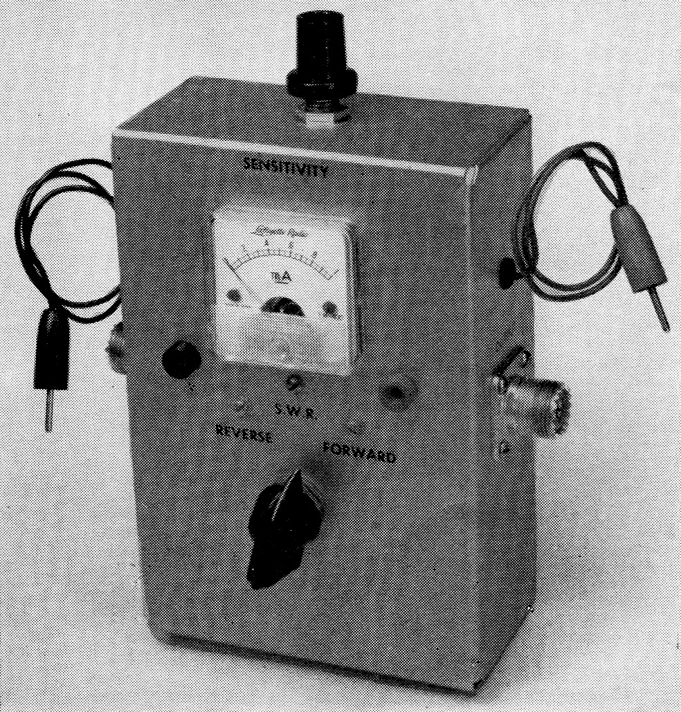
The standing-wave bridge is a v.h.f. version of the Monimatch, commonly used on lower bands. Test leads permit the bridge meter to be used for measuring grid and plate currents in the transmitters.
Solder the 1N34 diodes to the outside switch terminals, leaving connections no more than about 3 inch long. If you have the newer type diode, which is glass-enclosed and color-coded, the end with the black ring should go toward the switch. The other ends of the diodes connect to the ends of the wire that is threaded inside the braid. Make these connections short and direct, and be sure that the exposed leads are the same length on each side. The coax is draped in U shape, so that it just touches the inner end surface of the chassis. At this point the 47 ohm resistor is connected from the enameled-wire tap to a ground lug fastened at the center of the end wall of the chassis.
Placement of the other components is not critical. The sensitivity control, R1, is mounted in the top end of the chassis, and the meter hole is centered below it, 1½ inch down from the top edge of the main chassis surface. The two tip jacks are ¾ inch in from the edges of the chassis and 2½ inch down from the top. The switch is 2 inch up from the bottom.
Uses
The primary purpose of the bridge is to determine when the antenna system is properly matched to its feedline, but it also serves other ends. When in the for ward-power position, the meter gives a sensitive indication of the amount of power going through the transmission line, so it is useful in tuning up the transmitter. In fact, once the transmitter is operating according to the information given in Part 2, tuning can be done merely by watching the bridge meter while adjusting the final amplifier plate and loading capacitors for maximum indication.
The bridge should be connected between the antenna relay and the line to the antenna, as shown in Fig. 1, Part 1. V.h.f. antennas are usually designed to be fed with 50-ohm coaxial line, or 300-ohm balanced line. Various means for making the antenna present a 50-ohm load are beyond the scope of this series, but whatever the matching system is, it can be adjustad by setting the bridge switch in the reflected-power position and adjusting for minimum indication. Switch to the forward-power position intermittently and check the transmitter adjustments to see that they have not been thrown off by the change in load impedance occurring during antenna work.
If the antenna is fed with a balanced line, some form of balanced-to-unbalanced coupling system will be needed. Here, again, a detailed discussion of such devices is not attempted here, but the reader is referred to the ARRL Handbook and Antenna Book for more information. If the line is a 200 ohm type (rarely used), or the antenna presents a 200 ohm balanced load, a coaxial balun can be inserted at the point where it is desired to change from 50 ohm coax to 200 ohm balanced load or line. Information on the construction of a coaxial balun can be found in either of the above references. If the load is other than 200 ohm, the best means of matching between 50 ohm coax and any value of balanced load is an antenna coupler. This is a simple tuned circuit with a tuned link coupled to it. Again, the Handbook will give all necessary information. An advantage of the tuned antenna coupler is that it provides considerable rejection of unwanted frequencies that might cause interference to television and other services.
Interior view of the bridge. Symmetry and minimum length of r.f. leads are important in making this type of bridge work at 50 and 144 Mc.
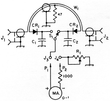
Fig. 6. Schematic diagram of the standing-wave bridge. Fixed resistors are ½ watt.
| C1,C2 | 1 nF button-style capacitor (Centralab ZA102). |
| CR1,CR2 | 1N34 diode. |
| J1,J2 | Coaxial receptacle, S0-239. |
| J3,J4 | Insulated tip jack. |
| P1,P2 | Insulated tip plug. |
| R1 | 5000 ohm control. |
| S1 | S.p.d.t. rotary switch (Centralab 1460). |
| W1 | 7¼ inch length of RG-58/U, with No. 24 enameled wire inserted as per text. Use Formvar-insulated wire if possible. |
It should be emphasized that an antenna coupler or antenna matching device should always be adjusted for minimum reflected power in the coaxial line. This should be zero or very close to it. The bridge is then switched to the forward-power position and the transmitter and toading adjustments are checked to be sure that the rig is delivering maximum power to the line. Adjustments to the transmitter have no effect on the standing-wave ratio on the transmission line. If the transmission line is long (over 50 feet or so) the bridge will give the most sensitive indication of matching adjustment if it is connected at or near the antenna. Where it is connected in the line will have no bearing on its effectiveness as a forward-power indicator.
The test leads must be plugged into the bridge tip jacks in order to read either forward or reflected power. These leads can be any convenient length, as they carry only a very small direct current. The bridge may be left connected in the antenna line while the meter is used for transmitter measurements, as removing the leads from the bridge tip jacks disconnects the meter from the bridge circuitry.
Checking modulation
Some kind of lamp load is helpful in observing the effects of modulation on the transmitters. Connect a crystal or high-impedance dynamic microphone to the modulator, and with the audio gain turned down, adjust the transmitter for maximum output indication as described on pages 33 and 34 of August QST. If the lamp load is made of several blue-bead pilot lamps connected in parallel, the bridge can also be used as an auxiliary indication of power output. If the load is a 115 volt lamp the mismatch may be too high to use the bridge effectively.
Advance the audio gain slowly while speaking into the microphone. As the gain is increased it will be seen that the brilliance of the lamp indication increases with speech. There should be appreciable brightening, but the plate and grid currents should not vary. Adjustment of the grid drive and the loading affect the ability of the transmitter to modulate properly. If the grid current is too high or too low, modulation may cause the currents to fluctuate, indicating that the voice quality will suffer and the transmitter may cause interference outside its normal pass-hand. Most effective modulation will be obtained at the highest gain setting that can be used without causing the plate or grid current to fluctuate.
It is possible that the modulation may be low, even if the transmitter is working properly, due to limited output from the modulator. The modulator will deliver 7 to 8 watt of audio without severe distortion. This means that the transmitter should not run much over 15 watt input if full modulation is to be achieved. If you get reports of "low modulation" from fellows you work, reduce the transmitter input slightly by detuning the loading capacitor and readjusting the plate tuning for the point that gives the greatest output with the least plate current. A current of 60 to 70 mA will be about all that the modulator will handle well, though on c.w. it will be possible to increase the loading to the point where the final stage runs 20 watt input or more. This is worth having, though the difference between it and the 15 watts that can be fully modulated will be just barely noticeable at the receiving end.
Edward P. Tilton, W1HDQ.