Performance tests on the big wheel 2 meter array
Stacking information and results with omnidirectional antennas.
In september QST W1IJD and W1FVY described a novel omnidirectional array for 144 Mc mobile or fixed-station work. These fellows are now engaged in ice research in the Far North, and there was not sufficient time for them to complete tests on stacked versions of the antenna before their scheduled departure, so the writer gladly took up where they left off. As is usual when one tries to get to meaningful numbers in connection with amateur antennas (and by amateur methods) this turned out to be no mean task.
On-the-air results are all that really count in evaluating the worth of antenna ideas for amateurs. Precise measurement of pattern and gain are all but impossible, but if an antenna "has what it takes," protracted use of it under many differing conditions will show its superiority clearly. The "many " in the above sentence bears emphasis. Routine comparisons of various antennas can show widely different results. In fact, if they don't there is probably something wrong with the tester's methods. Reflections from ground, trees, buildings, hills, cars and the like add to or subtract from the direct signal to such an extent that "gain" figures taken by working stations and comparing signal reports show large variations from one station to the next. These are part of everyday v.h.f. communication, so the thing to do is to work many stations at various distances and directions with a given comparison setup. Then, if you want to know for sure, you set up again in a different location and work another bunch. This is time-consuming, but interesting if one keeps a detailed log of the results.
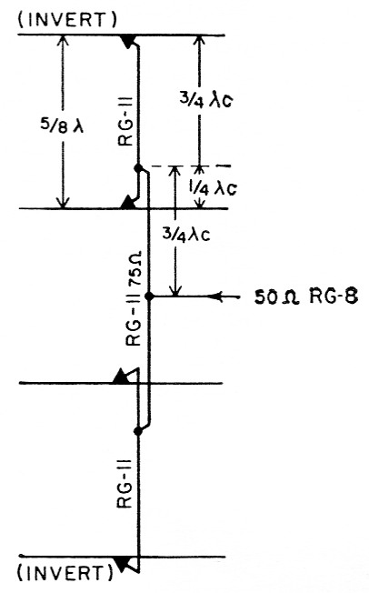
Fig. 1. Feed system for a 4 bay version of the Big Wheel 2 meter array. The two center bays are the same side up, while the two outer bays are inverted. Bays are approximately 5/8 wavelength apart physically, which permits the use of full-wave phasing sections between them. The feed points of each pair are then fed through two ¾ wave phasing sections, and a 50 ohm line at the midpoint sees an almost perfect match. The tuning stubs on the two inner bays (see September QST) are 7 inches long, while those on the outer bays are 6 inches.
The writer spent many hours at this sort of thing with the Mellen-Milner Big Wheel. Tests at the W1HDQ home location proved inconclusive, because of a side-hill test area, and trees, guy wires and towers in the way of anything that could be worked on readily. So, after the matching problems were worked out to our satisfaction, we took the collection of antennas and masts out to some of our favorite wide-open hilltops. The single-bay clover-leaf was mounted on a 15 foot mast. Two-bay and four-bay stacked arrays were tested on a 24 foot support. All were checked against the turnstile(1) regularly used for mobile work. This put the turnstile in a seemingly unfavorable light, as it was used in its permanent position some 20 inches above and to the rear of the W1HDQ station wagon. The turnstile had established itself as an effective mobile antenna, however, so it was useful as a standard reference for checking results with the larger and higher arrays.
Results
All told, around 100 different stations were worked or logged, and their signal strengths tabulated in terms of decibels above the readings obtained with the mobile turnstile. Care was taken to see that these stations were in various directions, at all possible distances, and well distributed throughout the active portion of the band. As expected, indications from these tests varied widely, but we feel that enough of them were made so that they are valid indications of what can be expected from various versions of the Big Wheel. It should be stressed that the margin credited to the single-bay Big Wheel over the turnstile is largely the result of the former having been mounted at considerably greater height. These tests were not intended to show the relative merits of the turnstile and Big Wheel; the turnstile was used merely to provide a reference against which all other setups could be compared. The tabulation below includes only received signal strengths at W1HDQ/1. Many reports were taken from stations worked, but individual S-meter readings varied so widely that no numerically-useful data could be obtained from them.
| Average gain, 1 bay clover leaf over turnstile | 5.7 dB |
| Average gain, 2 bay over 1 bay | 6.2 dB |
| Average gain, 4 bay over 1 bay | 8.1 dB |
The "gain " obtained with the 2-bay Big Wheel appears out of line, but more readings were taken with various versions of this array than any other, and we can assure the reader that the 2-bay version really does perform. Time and again, signals which could be heard only as faint whistles with a beat oscillator with a single-bay antenna jumped up to solid voice readability on the 2-bay version. These were not included in the tabulation, as the strength of the nonreadable signals could not be established readily - but they do show that a stacked Big Wheel does what everyone wants an antenna to do: it brings in signals that cannot be heard with simpler antennas. It should be emphasized, however, that these are not antenna-range measurements, and should not be interpreted as such.
The stacked versions proved to be nothing short of spectacular on signals coming from extreme distances. On one occasion a signal from a New York ar'a station was totally inaudible on the single-bay and the turnstile, yet it was a readable S3 on the 2 bay array. This was over an indirect hilly path of some 75 mile, and the test was made around 1 P.M. on a hot summer day, when tropospheric bending was at a minimum. Tests made at night often showed the 2 meter band loaded with weak signals, fading into and up out of the noise, when either the 2 bay or 4 bay stacks were switched to the receiver. Tuning the band with the turnstile and single-bay antennas under the same conditions would show only the strong signals of locals and near-locals. Many contacts were made at distances up to 100 mile or so from locations where long experience in the past has shown that some form of beam is a must for raising stations at anything like this distance.
We worked hard at trying to make the stacking of two pairs of antennas pay off as much again as did the stacking of two single bays, but this would not quite "come off." The indicated gain from the latter is more than would be expected on the basis of stacking theory, but it was there, over and over again, in unmistakable fashion. This is probably due to the nature of v.h.f. propagation, wherein lowering and narrowing of the vertical pattern pays off in surprising fashion on some paths. You get this when you begin stacking. More stacking pays off, but not so spectacularly as the first step.
But a gain of 8 dB with an omnidirectional antenna is not to be sneezed at. You'd have to put up a pretty fair Yagi to equal this - and remember the 4 bay Big Wheel gives the gain in all directions. This is not an unalloyed blessing, however. The stack of Big Wheels is fine for net activity and local rag-chewing, but its omnidirectional pattern and high gain can multiply QRM problems manyfold. The 2 meter band becomes a mass of heterodynes when the 4 bay stack is used in a good location in an area of high v.h.f. activity, especially when some tropospheric bending is present. Another feature on the debit side: interference from commercial signals in the v.h.f. range multiplies with an omnidirectional array of such beautifully broad frequency characteristics. We were forced to abandon work with the Big Wheels in one favorite location where there are two f.m. stations, a u.h.f. TV station, and various police and forestry-service relays. These non-amateur stations give little, if any, trouble in this fine mountain spot when a Yagi antenna is used.
The Big Wheel should prove a blessing in many types of 2 meter work, however. If you can take the jibes of pedestrians and passing motorists, a single Big Wheel should give you the best 2-meter mobile signal in your area. If you live in a spot where you can put up only one antenna, and rotators are out, a stacked Big Wheel will make the 2 meter band a lot more interesting for you than it ever was before. W1FVY and W1IJD showed how to make the individual bays, and the stacking method for two bays last month. The four bay version is shown herewith.
Reports following the appearance of the Big Wheel in QST last month indicate some confusion about the construction of the antenna. Referring to Fig. 3, page 44, of the September article, each element (A) runs from the grounded plate (B) to the triangular plate (C).
These two plates are mounted one above the other, at a spacing determined principally by available insulators. Ceramic standoffs 1 to 1½ inch long are suitable. The Johnson Steatite cone, part 135-501, 1 inch long, with 8-32 threads, is good. The designers also used a bakelite block 1 inch long, with molded-in brass inserts, though we do not have a part name or number for this.
The tuning stub (D) is shown bent around a ¾ inch radius, but this is not critical. Note that the stub length is 5 inch for a single bay. For a stacked 2 bay system the stubs should be 6 inch long. In a 4 bay array the top and bottom stubs are 6 inch and the inner pair 7 inch. For a single bay mounted above a metal car top for mobile work, a 6 inch stub may be needed.
Notes
- Campbell, "Turnstile for Two," QST, April, 1959, p. 29.