ALC for class AB1 amplifiers
This self-adjusting ALC circuit allows your amplifier to produce maximum power without splatter!
Although class-B cathode-driven triode amplifiers have achieved popularity, don't relegate the class AB1 grid-driven tetrode to the attic with the old spark transmitters! True, tetrode circuits involve a bit of extra work (the inclusion of bias and screen supplies), but tetrodes in AB1 amplifier service offer a number of important advantages:
- Low drive requirements; this is especially advantageous for VHF operation.
- The use of a loaded, untuned input circuit; this provides stability and precludes the need for neutralization. The untuned input is especially useful in a general-coverage amplifier. With the addition of the WARC bands, it is troublesome to provide switching for multiple-band input circuits. The un-tuned input may more than compensate for the need for bias and screen supplies.
- No fluctuating load on the driver; this promotes linearity.
- No filament choke is needed. Again, this helps compensate for the bias and screen supply requirements.
Chapter 31 of The 1986 ARRL Handbook and Chapter 22 of the Radio Handbook have excellent examples of high-power amplifiers using tetrodes.(1)(2)Detailed information on operating conditions is found in Robert Sutherland's book.(3) Most published designs, however, include no provision for ALC. Even more important than getting the maximum possible power from an amplifier is the obligation to produce a clean signal; that is, one that won't disturb other operators on the band. To obtain both of these objectives, it is essential to use ALC. There is absolutely no other way to get every syllable right up to peak output power without flat-topping.
Many ALC circuits in use involve critical balance or level controls that can be quite impractical to use, especially for contesting and quick band changing. A main feature of the circuit described here is the absence of any such adjustments; it is completely self-adjusting, reacting only to actual grid current and automatically adapting to changing conditions. The circuit can be built into a homemade amplifier or easily added to a commercial exciter or amplifier.
This circuit is used in all of my homemade tetrode amplifiers. One of these, tuning continuously from 1.8 to 54 MHz, uses a 4CX1000A with a 50-ohm passive-grid input circuit. The amplifier is absolutely stable and requires only 30 watts of drive; the original exciter tubes have survived 15 years of use and still show no signs of fatigue. A pair of 6146s drive the 4CX1000A at 50 MHz, but have their own ALC for "barefoot" operation. Another amplifier, using a pair of 4-400As in push-pull at 14.4 MHz, uses screen neutralization and does not present a fluctuating load to the driver.
Many older commercial amplifiers use audio-derived ALC; one example is the Collins 30S-1. In this amplifier, an audio transformer primary is placed in the tube's grid lead; current fluctuations during SSB operation produce a secondary voltage that is rectified to produce an ALC voltage. This method works well enough, but provides no ALC during tune-up or CW operation.
The circuit described here operates solely on the dc currents in the grid circuit; thus, it works in all modes. This is especially useful for tune-up and when used with tubes having sensitive grids; it prevents damage to the tube under all conditions. In the 4CX1000A amplifier mentioned earlier, a 1-mA meter relay is used to protect the grid, but in the 15 years of operation with the ALC circuit described here, the meter has never gone past the 0.1-mA mark. The ALC circuit alleviates the need for other means of protection. To protect the screen grid also, the screen protection part of the system described reference 4 can be used. For triode amplifier ALC circuits, see reference 5.
Circuit Description
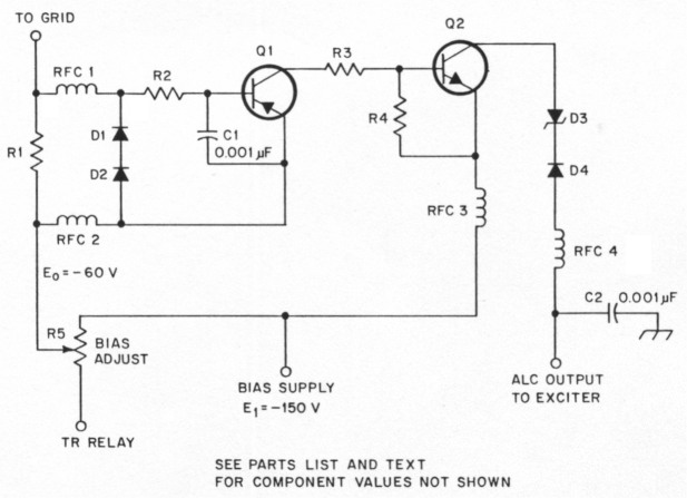
Fig 1 - Amplifier ALC circuit. Values shown are typical for a 4CX1000A. For use with other tubes, only R3 and D3 and the voltage ratings of the transistors need be changed; see text.
| D1, D2, D4 | 1N4007 |
| D3 | 130-V, 1-W Zener diode; see text. |
| R1 | 4.7 kΩ |
| R2 | 470 Ω |
| R3 | 100 kΩ; see text. |
| R4 | 10 kΩ |
| R5 | Existing bias control. |
| RFC1-4 | 1-mH RF choke for HF. Use lower values for a VHF amplifier. |
| Q1 | MPS-A92 or any PNP transistor with a 200-V or higher rating; see text. |
| Q2 | MPS-A42 or any NPN transistor with a 200-V or higher rating; see text. |
This circuit can be universally applied. Circuit variations depend only on the bias voltages used, not on the tube type. The circuit for bias-voltage levels such as those used with the 4CXI000A is shown in Fig 1. Grid current is sampled by R1, which acts somewhat like a meter shunt; the voltage developed across R1 turns on Q1. Approximately 0.1 mA of grid current is required to develop the 0.6 V needed to forward bias the base-emitter junction. With Q1 on, the operating bias voltage, E0, appears at the collector of Q1. The voltage at the emitter of Q2 is derived from a more negative ppint, Et. The difference between Et and Eo appears across R3, and the resulting current turns on Q2. Et then appears at the collector of Q2. The Zener diode, D3, in the output line reduces this voltage to a level that is comfortable for the exciter. The transistor types used for Q1 and Q2 are not critical. Q1 and Q2 are silicon PNP and NPN types, respectively, with voltage ratings above the level of the highest voltage in the circuit.
For class-C operation (with suitable tubes only), the ALC line is switched off and the amplifier is driven into high grid current. In this situation, protective diodes D1 and D2 in the input circuit limit the voltage drop across R1, and R2 then limits the Q1 base current. Isolating diode D4 in the output circuit ensures that there is no possibility of the amplifier ALC circuit loading the exciter circuits during barefoot operation. D4 also prevents any possible interaction between the different amplifier ALC circuits in my station, all of which are connected in parallel to the exciter ALC jack.
The voltage (E0) appearing at the collector of Q1 when it is turned on cannot be used directly for ALC. This is because without the higher negative voltage, E1, to reverse bias the base-collector junction, E0 will appear at the collector at all times, even without grid current.
Circuit Analysis
The important circuit components are R1 and R3. The value of R1 is not too critical; it is chosen as a compromise between the requirements of limiting the grid current to a low level and not introducing excessive resistance into the grid circuit. A value of 4.7 kΩ satisfies these requirements. I tried lower values of resistance at R1 for several years in one of my amplifiers, using a panel-mounted variable resistor to set the ALC level. No output power or distortion differences were noted using values of resistance between 500 to 5 kΩ, corresponding to a grid-current range of from 0.1 mA to 1 mA. No deterioration of amplifier operation has resulted from the insertion of 4.7 kΩ in the grid lead.
The value of R3 plays a more important role than may at first be apparent. An ALC circuit must act quickly at the first cycle of the first syllable of the voice signal to properly control the drive level. A typical exciter ALC input circuit is shown in Fig 2. We can insert no appreciable resistance in the collector of Q2 as this would cause a time delay in charging C101 in the exciter. On the other hand, we must prevent creating collector currents beyond the rating of Q2 while charging C101, or when the ALC cable is accidentally shorted (an uncharged C101 acts like a short). This is the role of R3; it is chosen, to produce a 1-mA base current in Q2. This limits the collector current to a safe value with any typical transistor that might be used and still provides fast charging of C101 and a consequential quick ALC attack time. For example, if Q2 has a gain of between 20 and 100, the collector-current limit will be between 20 mA and 100 mA.
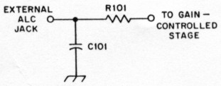
Fig 2 - A typical exciter ALC input circuit.
Circuit Variations
The only circuit changes required for use with various amplifiers are the value of R3, the voltage ratings of the transistors and the output Zener diode ratings. D3 has a voltage rating of approximately 20 V less than Et; this allows a maximum of 20 V to reach the exciter. The value of R3, measured in kilohms, is numerically equal to the difference between the standby and operating biases, E1 and E0, respectively. The exact value of R3 need only be approximate. Thus, a 4-400A amplifier with a 300-V standby bias and 150-V operating bias would use a 150-kΩ resistor at R3 and an output Zener diode (D3) rated at about 280 V. (Whatever Zener diodes you have in your junk box can be used to make up a series arrangement at roughly the desired voltage.) If screen-voltage switching is used for standby, the available bias supply voltage is used for Q2; this was called "standby bias" earlier for easy reference; any available voltage more negative than the operating bias will suffice. For example, an 8122 amplifier with screen standby control, and a constant 20-V operating bias, uses the 60-V bias supply at the emitter of Q3, a 39-kΩ resistor at R3 and a 39-V Zener for D3.
The output Zener has a value that is more psychological than electronic. One of my amplifiers worked for 10 years with no Zener without a bit of trouble-except an occasional worry. In fact, there is almost no way for the full bias supply voltage E1 to appear at the exciter. As soon as the ALC voltage rises far enough to limit the exciter gain so as to reduce the amplifier drive to the grid-current threshold level, the current in Q1, and the base current in Q2, are reduced so that Q2 will provide all the voltage drop required. However, D3 does provide protection for the exciter in the event of a short in Q2. Also, D3 reduces the dissipation in Q2. Since the circuit has been used only with an exciter whose ALC circuit requires less than 0.1 mA, the dissipation in Q2 has not been a problem. Usually R101 is fairly large; hence, there should be no dissipation problems. But if an exciter requires a significant amount of current, the dissipation in Q2 must be calculated.
It is easy to test the exciter by applying the required negative ALC voltage at the exciter ALC jack with a test supply and measuring the current required to swing the ALC meter. The required power rating for D3 can then be calculated. If a transistor with a higher dissipation rating is required for Q2, try an MPS-U10. At slightly higher cost, the high-quality 2N5416 and 2N3439 can be used for QI and Q2, respectively.
Although I haven't tried it, this circuit can be used for class-AB2 operation. To obtain a higher grid-current threshold, simply decrease the value of R 1.
Installation
If the ALC circuit is installed in the wrong part of the amplifier grid circuit, the emitter-base current of Q2, supplied by E1 and returned through Q1 to the operating bias point at level E1, will appear on the grid-current meter. To avoid this, the grid-meter shunt should be between the ALC circuit and the grid, as shown in Fig 3.
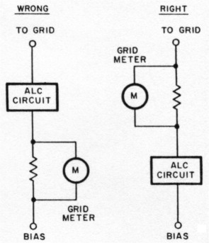
Fig 3 - ALC circuit installation. See text.
When the ALC circuit is installed in an existing amplifier, a handy retrofit method is to build the circuit on a small plug-in circuit board. In this case, it is best to permanently install R1 in the amplifier circuit. Then, if the board is removed for testing, there will still be bias applied to the tube. To reduce the value of R1 , you need merely shunt it with another resistor on the board, leaving the original RI in the amplifier.
Operation
Between its grid-current sampling shunt, R1, and the exciter ALC circuit, the ALC circuit may be considered a high-gain dc amplifier. In effect, the ALC meter operates as an extremely sensitive grid-current meter, and you shouldn't be surprised if full ALC indications are obtained while almost nothing at all can be seen on the grid-current meter. The action of the grid-current meter will depend on its range and the meter damping.
On VHF, where the secondary emission effect of the tubes is more pronounced, the ALC meter may indicate normally, representing a 0.1-mA grid current, while the grid meter registers negatively. That's okay. The ALC circuit reacts only to the normal grid current at the peak of the RF drive cycle, while the meter reads the average current over an entire cycle, which is negative. This situation is clarified by the discussion and curves on pages 11 through 13 of reference 3.
The ALC circuit can be tested with the high voltage off, when the secondary emission effect is absent. Two-tone tests (using a dummy load) were run on 2 meters while reducing the value of RI until very small positive grid-current-meter indications were obtained simultaneously with normal ALC meter indications. Severe flat-topping was evident on the monitor scope, and splatter far up and down the band resulted. What this means is that the ALC circuit protects against overdrive that can't even be seen on the grid-current meter. The meter reads the average grid current. We want the grid current to go just an infinitesimal bit positive at the peak of the RF cycle, but not so positive so as to be greater than the negative grid current caused by secondary emission.
Although this circuit looks like a switch that abruptly turns on the ALC voltage at the instant the grid current reaches the threshold level, in practice the operation is extremely smooth. The reason for this is that the ALC loop gain is not determined by the amplifier ALC circuit, which has very high gain, but by the gain-control characteristics of the exciter stage controlled by the ALC. The action between the exciter DRIVE control and the ALC voltage as indicated on the exciter meter is just the same as when the exciter is operated barefoot; you can forget you have ALC in the amplifier.
This circuit has been used in my amplifiers for 15 years, with no trouble and no reports of splatter. All circuit values are noncritical, and large changes in bias levels and idling current may be made with no ALC circuit changes. Best of all, there are no adjustments to make! This certainly is a "build-and-forget" circuit - I forgot to write this article for 15 years! I want to thank Bill Orr, W6SAI, and Bob Sutherland, W6PO, for their helpful suggestions on operating tetrodes.
Notes
- The ARRL 1986 Handbook for the Radio Amateur (Newington: ARRL, 1985).
- W. Orr, Radio Handbook (Indianapolis: Howard W. Sams & Co, 22nd ed, 1981).
- R. Sutherland, Care and Feeding of Power Grid Tubes, Varian, San Carlos, CA, 1967.
- M. Mandelkern, "High SWR Protection for Transceivers and Amplifiers," CQ, May 1980, pp 63-65.
- J. F. Riley, "Improving Amplifier ALC Circuits," Parts 1 and part 2, Ham Radio, Aug 1984, pp 40-44, and Sep 1984, pp 52-56.
KN5S, Mark Mandelkern.